Break Lines Engineering Drawing
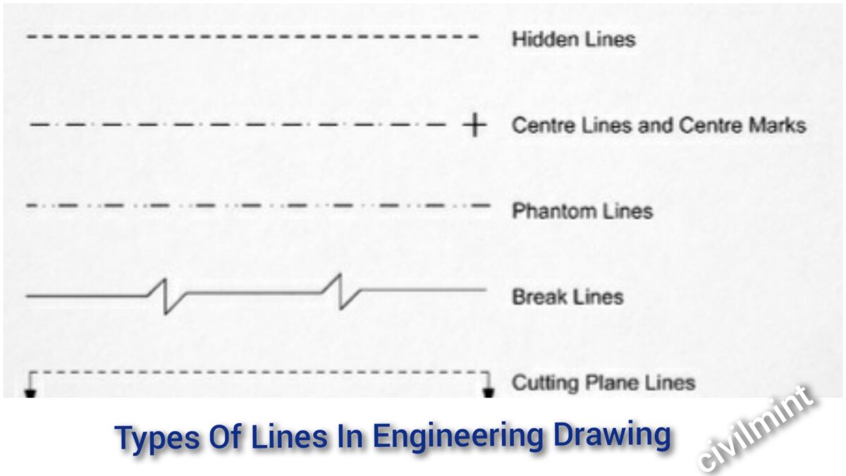
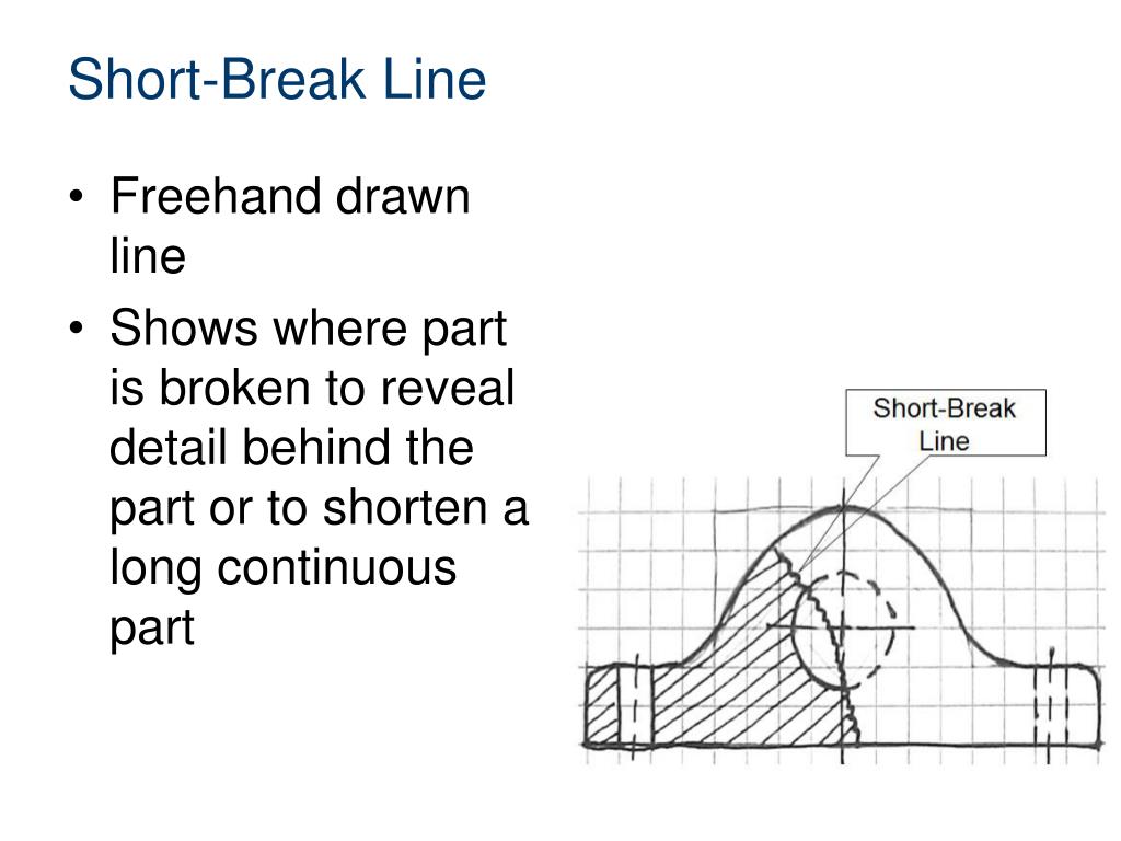
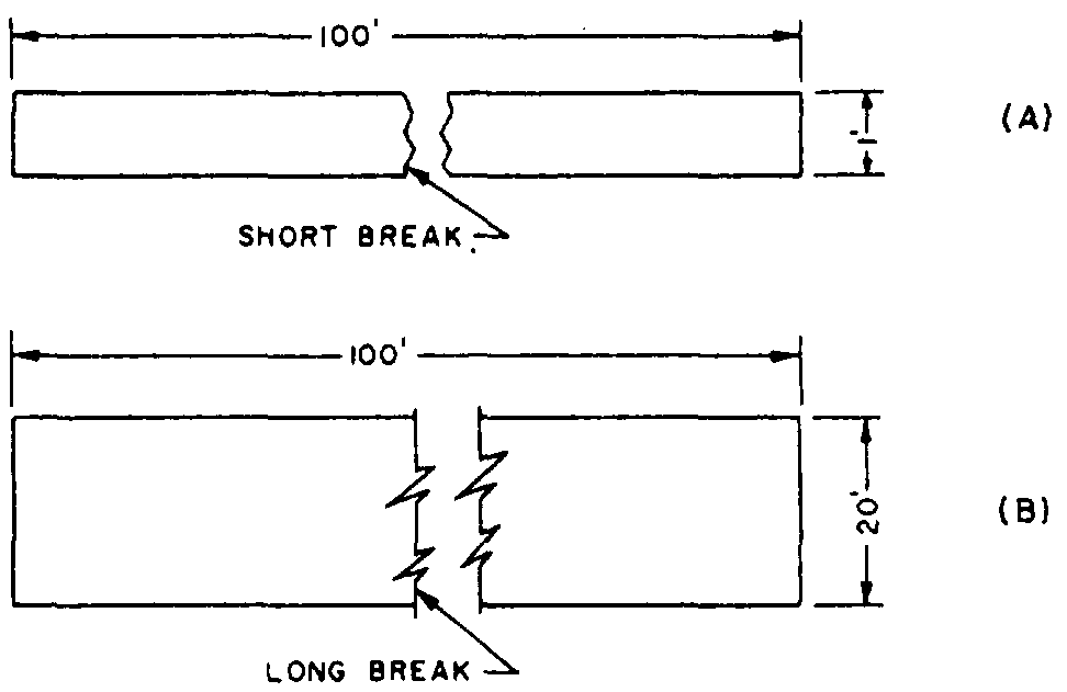
Break Lines Engineering Drawing - Web basic types of lines used in engineering drawings. Used to break the edge or surface of a part for clarity of a hidden surface. For example, electrical engineers draw circuit schematics and circuit board layouts. These lines are drawn to represent hidden or invisible edges of the objects. Web technically drawn 2 lines, lettering, and dimensions camosun college learning objectives by the end of this chapter, you should be able to: Section lines (hatching) are used in section views to represent surfaces of an object cut by a cutting plane. There are three types of break lines, each with a distinct line weight: This makes understanding the drawings simple with little to no personal interpretation possibilities. Web an engineering drawing is a subcategory of technical drawings. They are used to remove, or ‘break out” part of a drawing for clarity, and also to shorten objects which have the same shape throughout their length and may be too long to place on the drawing. A quiz completes the activity. Or other features with symmetric properties without cluttering the drawing. Section lines (hatching) are used in section views to represent surfaces of an object cut by a cutting plane. Web an engineering drawing is a subcategory of technical drawings. Used to break the edge or surface of a part for clarity of a hidden surface. There are various types of views in an engineering drawing. In this highly interactive object, learners associate basic line types and terms with engineering drawing geometry. If it does not, there is one other place to look to make sure the appropriate property is set. Also known as object lines, visible lines define the features that will be clearly visible. They are dark and thick lines of any engineering design drawing. Let’s explore some of the most common types of lines used in engineering drawings: Web the most common types of lines in engineering drawings include: Or other features with symmetric properties without cluttering the drawing. Visible lines are the most fundamental type of lines used in engineering drawings. All thick lines are usually drawn 0.6 mm thick. Identify line types used in technical drawings interpret dimensioning on technical. Also known as object lines, visible lines define the features that will be clearly visible in a particular view. Hidden lined (thick) hidden lined (thick) type lines consist of thick short dashes, closely and evenly spaced. They are used to. They define the outline or contour of the object. Extension lines can annotate an area that is being measured. Web break lines are drawn to show that a part has been shortened to reduce its size on the. For example, electrical engineers draw circuit schematics and circuit board layouts. Also known as object lines, visible lines define the features that. They are used to remove, or ‘break out” part of a drawing for clarity, and also to shorten objects which have the same shape throughout their length and may be too long to place on the drawing. There are various types of views in an engineering drawing. For example, electrical engineers draw circuit schematics and circuit board layouts. Web technically. All thick lines are usually drawn 0.6 mm thick. On the end opposite the arrow, the leader line will have a short, horizontal shoulder. The purpose is to convey all the information necessary for manufacturing a product or a part. There are three types of break lines, each with a distinct line weight: Short and long break lines are used. Short and long break lines are used for flat surfaces. Web table of contents types of lines 1. They define the outline or contour of the object. Three types of break lines with different line weights: This makes understanding the drawings simple with little to no personal interpretation possibilities. On the other hand, break lines show a broken view without taking too much space. Engineering drawings use standardised language and symbols. The other end, without an arrow, terminatesat the point used as the center in drawing the arc. Web break lines are drawn to show that a part has been shortened to reduce its size on the. This makes. Why not just use a 3d model? These lines are drawn to represent hidden or invisible edges of the objects. Continuous lines represent an object’s physical boundaries. Used to break the edge or surface of a part for clarity of a hidden surface. The purpose is to convey all the information necessary for manufacturing a product or a part. If a part needs to be shortened with a. These lines indicate when a view has been broken. Engineering drawings come in many forms. Simply checking this option on should put the breaks across the dimension lines it crosses. Engineering drawings use standardised language and symbols. There are various types of views in an engineering drawing. Continuous lines represent an object’s physical boundaries. Break lines are used to separate sections for clarity or to shorten a section. Web if you choose the leaders tab, there is an option to ‘break lines’. On the end opposite the arrow, the leader line will have a short, horizontal shoulder. Short and long break lines are used for flat surfaces. Different types of engineering drawing views. By kelly curran glenn sokolowski. Web the continuous thin zigzag line shows a break line. Web engineering lines can be classified into several categories based on their purpose and representation. Visible lines are the most fundamental type of lines used in engineering drawings.
Break Line Architecture Drawing Short Break Line In Engineering

Types Of Lines In Engineering Drawing

DRAWING BASICS

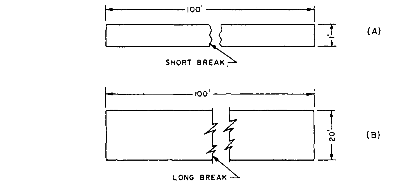
short and long break lines

AUTOCAD 2020 BREAKLINE SYMBOL HOW TO DRAW BREAK LINE SYMBOL YouTube

Different Types of LINES in Engineering Drawing//Classification of

How to draw a break line

short break line drawing examples pdf

Engineering Drawing 2 Ch4 Conventional break YouTube

short break line drawing example cover
Each Engineering Field Has Its Own Type Of Engineering Drawings.
A Quiz Completes The Activity.
Web Break Lines Come In Two Forms:
Web Line Conventions By Manufacturinget.org · July 28, 2011 Line Types (See Also Asme Y14.2M) When You Are Preparing Drawings, You Will Use Different Types Of Lines To Convey Information.
Related Post: