Component Drawing Example
Component Drawing Example - An engineering drawing can be used as a starting point for the creation of more comprehensive manufacturing drawings, manufacturing blueprints, mechanical drawing, dimensional prints and more. To draw a component drawing, the following steps should be taken: Web the drawings also detail larger components like roof trusses, kitchens and joinery for example, and form a type of instruction manual during construction. Double click the symbols and text the information. For example, a schematic diagram of an electrical circuit will show how the wires and components are connected without photographs of the circuit itself. Drag and drop relevant uml symbols from left libraries or click the floating buttons to add automatically. Web you can use a component diagram example below to get a quick start. Overview and explanation of the basic elements for a component diagram. It contains scaled views together with dimensions and notes. The figure below show's the store's component nested structure. Web 3.1 function 3.2 views bill of materials 4.1 contents 4.2 location 4.3 standard format drawing numbers drawing sheets 6.1 sizes 6.2 order 6.3 binding title blocks 7.1 location and contents 7.2 arrangement 7.3 drawing template revision blocks 8.1 location and content 8.2 standard format dimensioning 9.1 units 9.2 tolerances 9.3. Web a technical drawing is a detailed illustration of. This is just an introduction. Web a technical drawing is a detailed illustration of existing or newly designed components which are required, for example, for the manufacture of complex machinery. Web list the important components of a detail drawing. To identify all the parts; Web what is assembly drawings? Web the following table lists the most important elements for a component diagram in uml 2.0: An assembly or subassembly drawing showing all the standard and nonstandard parts in a single drawing. Beams, windows, doors, sills, coping stones, and so on. Draw a box or outline to represent the general shape of the overall product. The figure below show's the. What is component diagram component diagrams are used to visualize the organization of system components and the dependency relationships between them. It helps you create professional and impressive software design blueprints easily and quickly. Web the following table lists the most important elements for a component diagram in uml 2.0: List the paper sizes used for a detail drawing. To. Web for example, in a realistic landscape drawing, a leading line can be a pathway, a river, a row of trees, or a fence. What is component diagram component diagrams are used to visualize the organization of system components and the dependency relationships between them. In the past, architects would combine location drawings, assembly drawings and component drawings all in. That was possible because building techniques were less detailed. List the paper sizes used for a detail drawing. Schematic diagrams include only necessary details. To draw a component drawing, the following steps should be taken: Components of an engineering drawing. Drag and drop relevant uml symbols from left libraries or click the floating buttons to add automatically. Web even the most basic components require a lot of drawings to fully describe them. Based on the abovementioned criteria, in general, a complete set of working drawings for an assembly includes: Detail drawings of each nonstandard part. Beams, windows, doors, sills, coping. Visual paradigm online is a great piece of uml software for people who want to jump in and design. Drag and drop relevant uml symbols from left libraries or click the floating buttons to add automatically. Web for example, in a realistic landscape drawing, a leading line can be a pathway, a river, a row of trees, or a fence.. Web 3.1 function 3.2 views bill of materials 4.1 contents 4.2 location 4.3 standard format drawing numbers drawing sheets 6.1 sizes 6.2 order 6.3 binding title blocks 7.1 location and contents 7.2 arrangement 7.3 drawing template revision blocks 8.1 location and content 8.2 standard format dimensioning 9.1 units 9.2 tolerances 9.3. Assembly drawings show the entire device or system, as. In the past, architects would combine location drawings, assembly drawings and component drawings all in one sheet. Drag and drop relevant uml symbols from left libraries or click the floating buttons to add automatically. Visual paradigm online is a great piece of uml software for people who want to jump in and design. The roles of an assembly drawing include. Web we will treat “sketching” and “drawing” as one. Describe the organization and relationships between components using interfaces, ports, and dependencies. Web ultimate guide to component diagrams in uml including their benefits, how to use them, an overview of component diagram shapes and symbols, and even examples you can modify! Web component drawings are used to show how each part of a product or system is constructed. Component drawings provide detailed information about the individual units. Double click the symbols and text the information. The roles of an assembly drawing include component identification, assembly order labeling, and occasionally even standard requirements. Web component drawings might describe units such as; When properly rendered, the eye follows this line (or lines) directly into and through the drawing. That was possible because building techniques were less detailed. Web list the important components of a detail drawing. Schematic diagrams include only necessary details. Draw a box or outline to represent the general shape of the overall product. It helps you create professional and impressive software design blueprints easily and quickly. Web the pcb assembly drawing shows elements such as part outlines and reference designators the pcb assembly drawing table of contents an assembly drawing can be made in several forms so as to be the most convenient, and accurate for the manufacturer you work with. Components of an engineering drawing.
Assembly Drawing Practice For Free Download Assembly Drawing
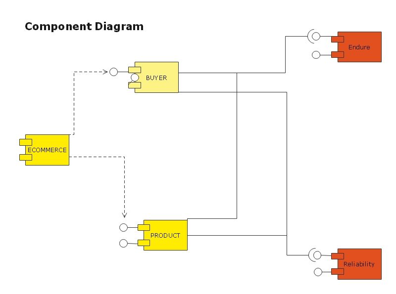
Component Diagram Explained EdrawMax Online
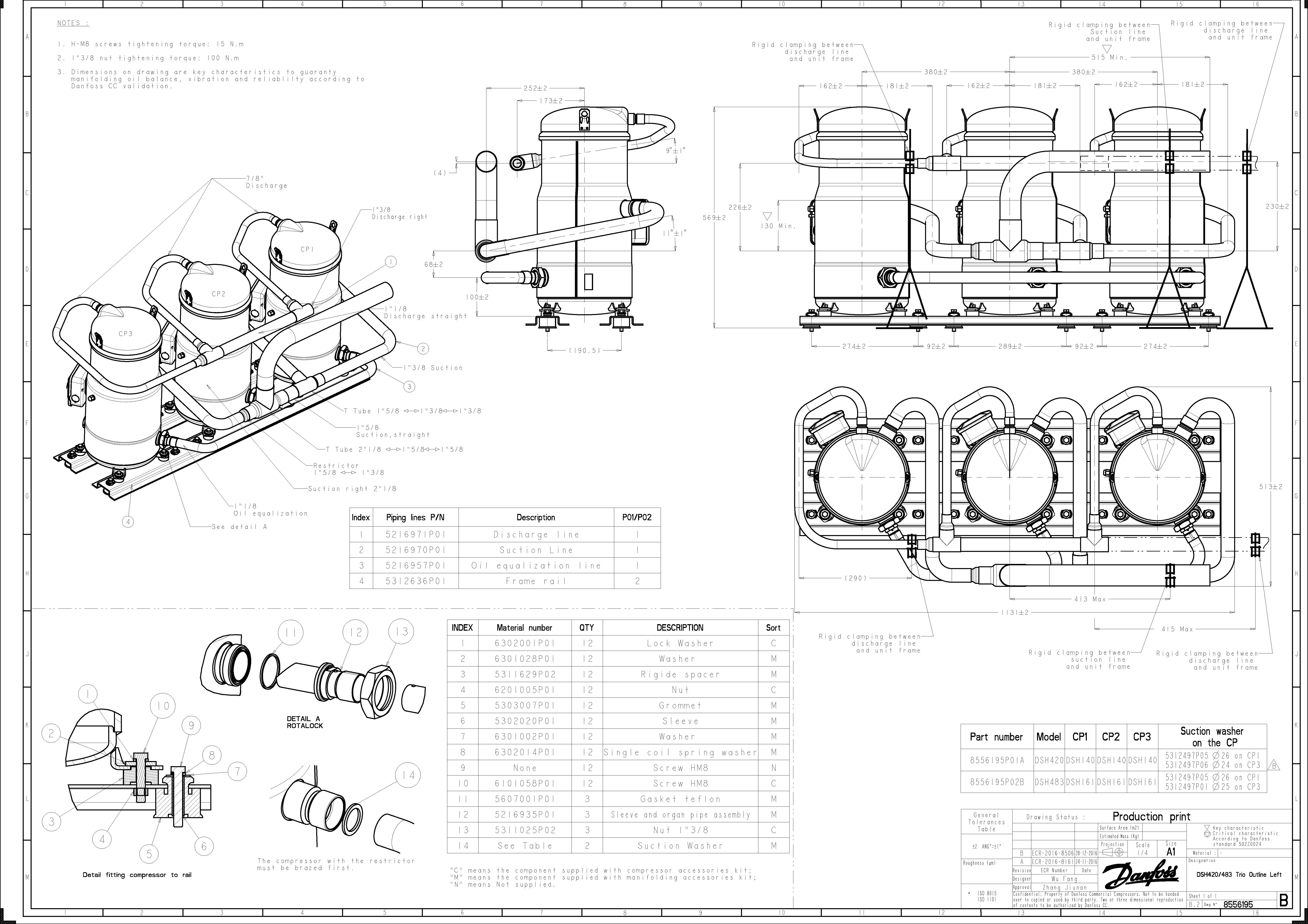
Component Drawing at GetDrawings Free download

detailed assembly drawing Buscar con Google Mechanical engineering

Resultado de imagen de detailed assembly drawing Mechanical
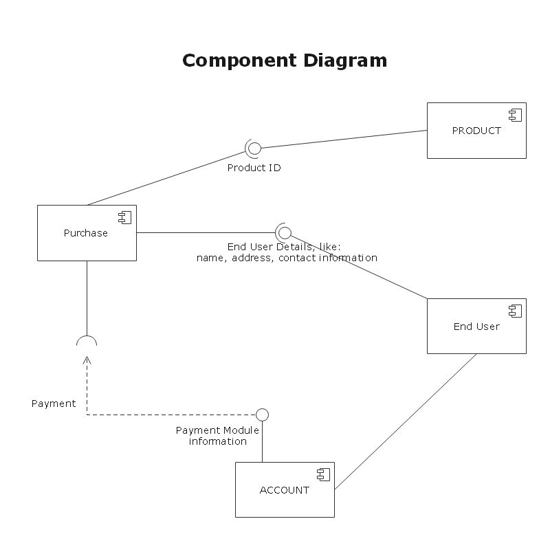
Component Diagram Explained EdrawMax Online

Lecture Notes Engineering Drawing Part 5
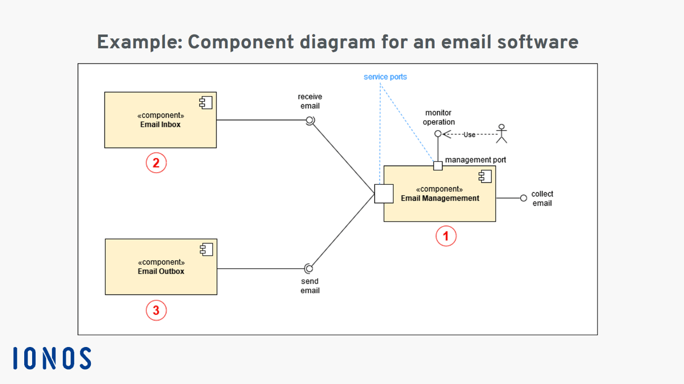
Uml Component Diagram Gambaran
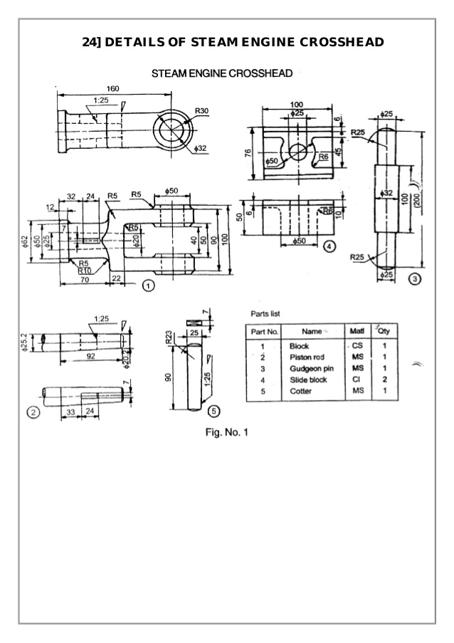
Component Drawing at Explore collection of

Component drawing used in the RIED pretest. Download Scientific Diagram
List The Paper Sizes Used For A Detail Drawing.
An Assembly Or Subassembly Drawing Showing All The Standard And Nonstandard Parts In A Single Drawing.
Every Engineering Drawing Is Different Depending On Its Usability.
Web The Drawings Also Detail Larger Components Like Roof Trusses, Kitchens And Joinery For Example, And Form A Type Of Instruction Manual During Construction.
Related Post: