Dimension Lines In Engineering Drawing
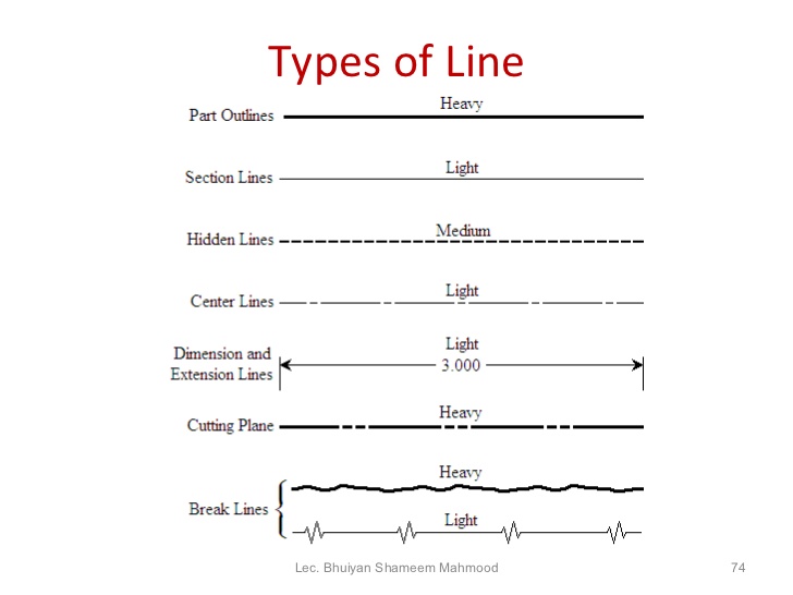
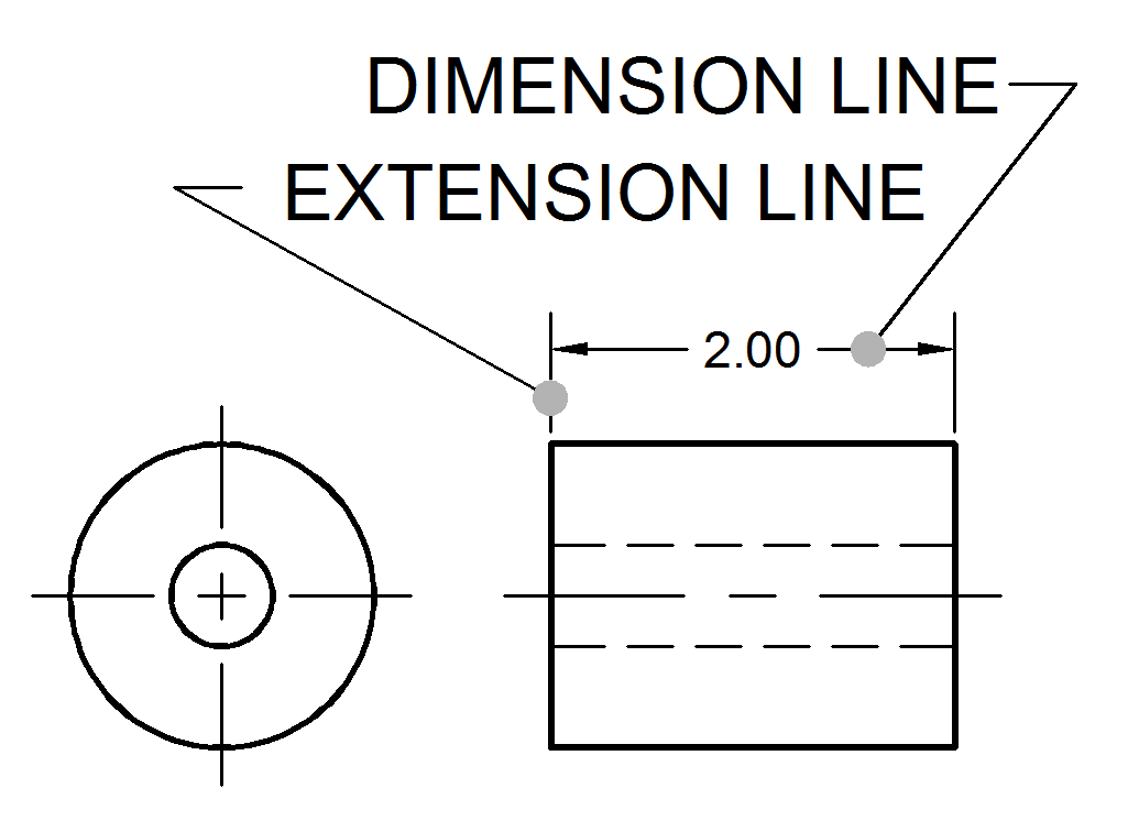
Dimension Lines In Engineering Drawing - When drawn under these guidelines, the lines parallel to these three axes are at their true (scale) lengths. Web dimensions in engineering drawings are shown in units of length and angle. Arrowsare placed at the ends of dimension lines to show the limits of the dimension. Two systems are used for dimensioning drawings. Elements of dimensioning it includes projection line, leader line, termination of the dimension line, the origin indication, symbols and the dimension itself. In figure 3.15, these dimension lines are the length of the dimension itself, i.e. Definition of rationality of dimensions on part drawing: Dimension lines are used to indicate the size and location of features in an engineering drawing. Extension lineis the thin solid line perpendicular to a dimension line indicating which feature is associated with the dimension. Web separate one line of dimensions from another line of dimensions or from a notation by a space of at least 10 mm (3/8). Web technically drawn 2 lines, lettering, and dimensions camosun college learning objectives by the end of this chapter, you should be able to: Dimension lines are drawn with an arrowhead at both ends. Web separate one line of dimensions from another line of dimensions or from a notation by a space of at least 10 mm (3/8). Dimension notesall dimensions. Web dimension and extension lines (figure 2.1. Arrows — symbols at the ends of dimension lines showing the limits of the dimension, leaders, and cutting plane lines. The width of engineering drawing lines can be one of the following depending on the type and size of the technical drawing. Extension line — a thin, solid line perpendicular to a dimension. Web dimension lineis the thin solid line which shows the extent and direction of a dimension. Only design sizes are shown as dimensions in engineering drawings. Web projections and dimension lines should be drawn as thin continuous lines. The dimension values are preferably placed near the middle of the dimension lines. Web technically drawn 2 lines, lettering, and dimensions camosun. Web the purpose of engineering drawings is to convey objective facts, whereas artistic drawings convey emotion or artistic sensitivity in some way. Break lines indicate that a view has been broken. When drawn under these guidelines, the lines parallel to these three axes are at their true (scale) lengths. It may seem a bit basic, but a few exercises with. Meet the design requirements and ensure the service performance of components; Two systems are used for dimensioning drawings. Arrowsare placed at the ends of dimension lines to show the limits of the dimension. The dimension values are preferably placed near the middle of the dimension lines. Rationality of part dimensions the dimensions in the part drawing shall not only meet. In figure 3.15, these dimension lines are the length of the dimension itself, i.e. A numerical value which is a length or an angle. The dimension line is a fine, dark, solid line with arrowheads on each end. Engineering drawings and sketches need to display simplicity and uniformity, and. Extension line — a thin, solid line perpendicular to a dimension. Web a line perpendicular to the extension lines, called a dimension line, with arrows at its endpoints, is shown between, and terminating at, the extension lines. Engineering drawings and sketches need to display simplicity and uniformity, and. Web a dimension is a number in a standard unit of measure shown on a drawing to indicate size, location, or orientation of. Dimension lines are used to indicate the size and location of features in an engineering drawing. Web projections and dimension lines should be drawn as thin continuous lines. Web some examples of the notes used in working drawings are as follows: Rationality of part dimensions the dimensions in the part drawing shall not only meet the requirements of correctness, integrity. Two systems are used for dimensioning drawings. Web a line perpendicular to the extension lines, called a dimension line, with arrows at its endpoints, is shown between, and terminating at, the extension lines. Engineering drawings and sketches need to display simplicity and uniformity, and. Projection lines should extend slightly beyond the respective dimension line. One meter (1 m) is equal. Web the dimension line has two arrowheads between the extension lines and the measurement on top (or inside, like in the image above) the line. Web dimension and extension lines (figure 2.1. Dimension lines are drawn with an arrowhead at both ends. It is indicated by arrowheads, it is drawn parallel to the surface whose length must be indicated. Dimension. Extension lineis the thin solid line perpendicular to a dimension line indicating which feature is associated with the dimension. Meet the design requirements and ensure the service performance of components; Extension lines are used to indicate the boundaries of a feature to which a dimension is applied. Web the gsfc engineering drawing standards manual is the official source for the requirements and interpretations to be used in the development and presentation of engineering drawings and related documentation for the gsfc. Web dimension and extension lines (figure 2.1. Dimension lines are drawn with an arrowhead at both ends. Identify line types used in technical drawings interpret dimensioning on technical drawings use professional lettering techniques Break lines indicate that a view has been broken. Web dimension lineis the thin solid line which shows the extent and direction of a dimension. One meter (1 m) is equal to one thousand millimeters (1000 mm). Two systems are used for dimensioning drawings. Note that the line width of any one line must be constant throughout the complete line. Web dimension, extension, and leader lines dimension lines. The mechanical engineering branch, mechanical systems division, has been delegated Leave a space of approximately 3 mm (1/8) between the object outline and the beginning of any extension line. Projection lines should extend slightly beyond the respective dimension line.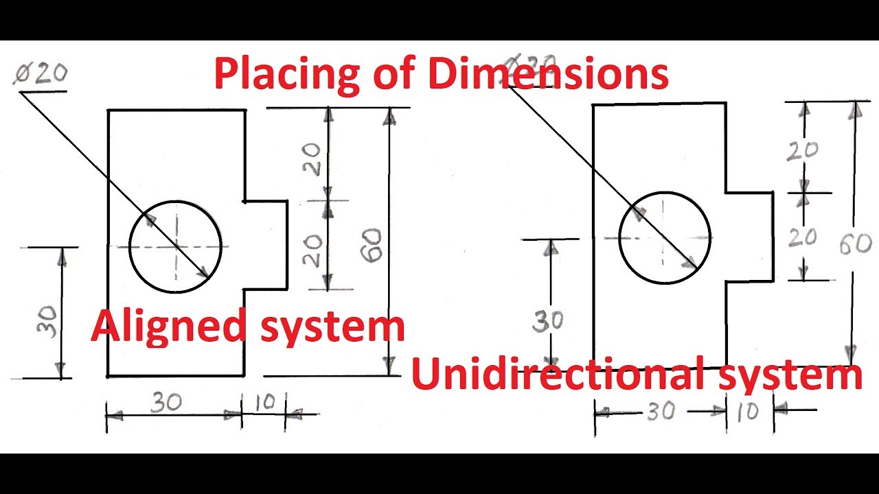
1.4aPlacing of Dimension Systems in Engineering Drawing Aligned and
Types Of Dimensions In Engineering Drawing at GetDrawings Free download
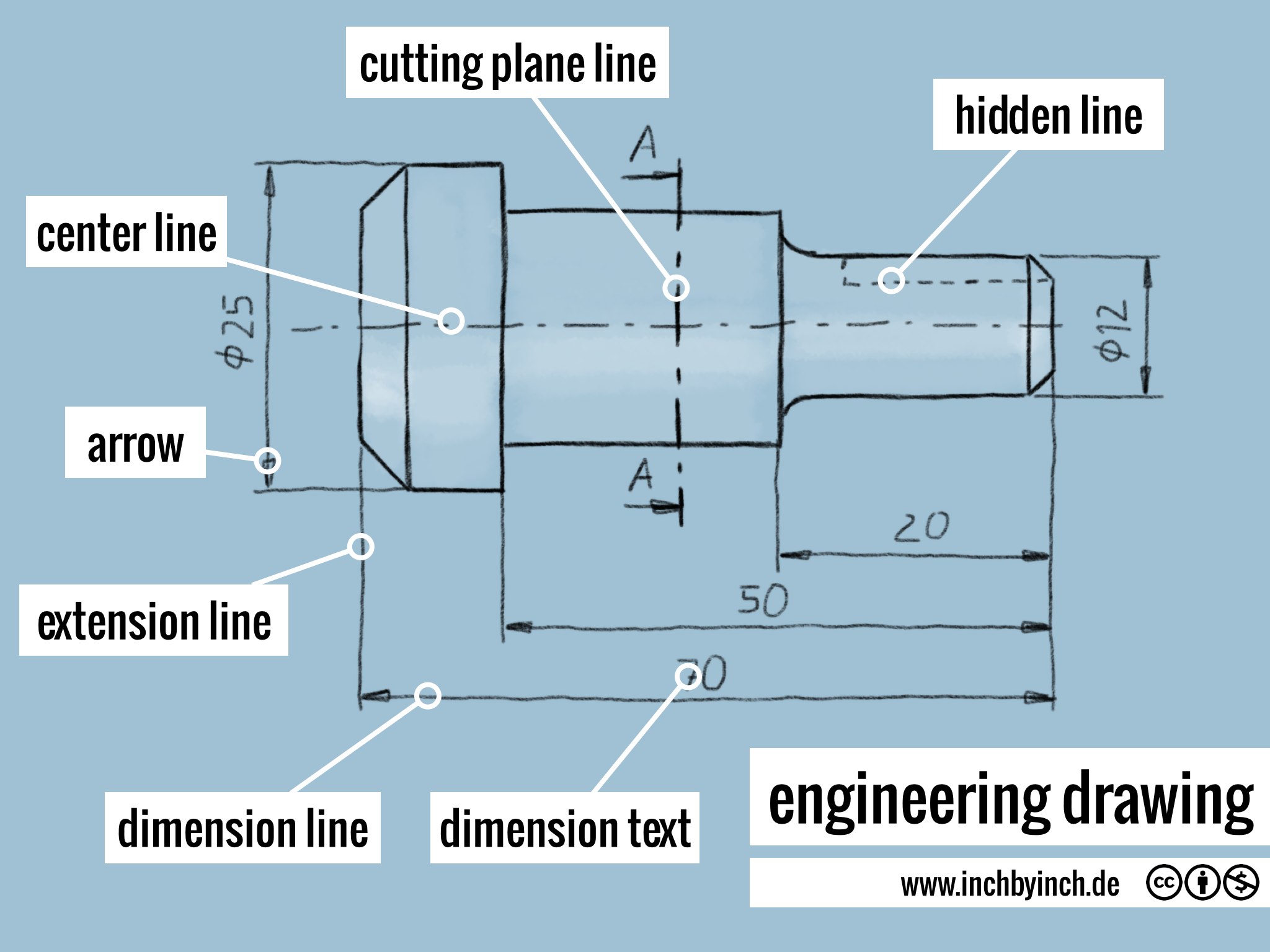
INCH Technical English engineering drawing
Engineering Drawing 8 Tips to Improve Engineering Drawing Skills
Dimension and Extension Lines ToolNotes

Types Of Dimensions In Engineering Drawing at GetDrawings Free download

Dimension Lines YouTube

Engineering Drawing Dimensioning Part 1 YouTube

Types Of Dimensions In Engineering Drawing at GetDrawings Free download

Lecture Notes Engineering Drawing Part 4
'50' Or '32' Mm Long.
When Drawn Under These Guidelines, The Lines Parallel To These Three Axes Are At Their True (Scale) Lengths.
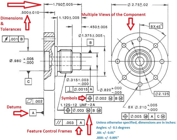
Elements Of Dimensioning It Includes Projection Line, Leader Line, Termination Of The Dimension Line, The Origin Indication, Symbols And The Dimension Itself.
Arrowsare Placed At The Ends Of Dimension Lines To Show The Limits Of The Dimension.
Related Post: