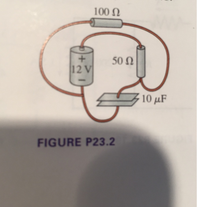
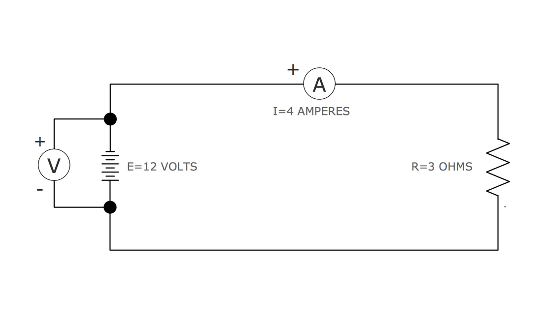
Draw A Circuit Diagram For The Circuit Of Figure 1
Draw A Circuit Diagram For The Circuit Of Figure 1 - Inputs x and c lead into an or gate. Web study the circuit diagram shown in figure 1 using the unique component values for r1, l1, c1 and the ac supply (vs) allocated to each learner in table 1. 10μf 12 v 50 ω 100 50 0 10μf 12 v 100 ww 50 12 v figure 1 of 1 100 ω 10μf 100 100 + 50 12 v 12 v 50 10 μf 10μf ww www + +. Learn for free about math, art, computer programming, economics, physics, chemistry, biology, medicine, finance, history, and more. There are other euler circuits for this graph. This problem has been solved! Draw a circuit diagram for the circuit of (figure 1). The reduced circuit shows resistors r2 and r34 are in parallel, with an equivalent resistance of r234 = 5ω. This is a circuit that travels over every edge once and only once and starts and ends in the same place. Web the circuit diagram is the language of electrical design and engineering. Web engineering electrical engineering electrical engineering questions and answers figure 1 table 1 4) draw the timing diagram for the circuit shown in figure 1 with the delay of each gate as provided in table 1. This is just one example. Web here, we note the equivalent resistance as req. Circuit diagram is a free application for making electronic circuit. Identify the components in the circuit: Web the circuit diagram is the language of electrical design and engineering. Web circuit symbols and circuit diagrams. Thus far, this unit of the physics classroom tutorial has focused on the key ingredients of an electric circuit and upon the concepts of electric potential difference, current and. Battery potential view the full answer step. These diagrams are maps that anyone can read to see how to build the circuit. This problem has been solved! Circuit diagram simple electric draw bulb switch cell showing question cludingsolved draw a circuit diagram for the circuit of (figure 1). The reduced circuit shows resistors r2 and r34 are in parallel, with an equivalent resistance of r234 = 5ω.. Draw a circuit diagram for the circuit of (figure 1). These diagrams are maps that anyone can read to see how to build the circuit. Electric circuit drawing at getdrawings | free download. Now, let's draw the circuit diagram using standard symbols for each component: The reduced circuit shows resistors r2 and r34 are in parallel, with an equivalent resistance. Web thus, the switch is in off position and the circuit is not closed. You'll get a detailed solution from a subject matter expert that helps you learn core concepts. When engineers design or build any electrical circuit they either create a new circuit diagram or use an existing one. This is a circuit that travels over every edge once. The reduced circuit shows resistors r2 and r34 are in parallel, with an equivalent resistance of r234 = 5ω. Inputs x and c lead into an or gate. When engineers design or build any electrical circuit they either create a new circuit diagram or use an existing one. Learn for free about math, art, computer programming, economics, physics, chemistry, biology,. Inputs a and b lead into an and gate with output x. Web calculations from circuit diagrams. Battery potential view the full answer step 2 final answer previous question next question transcribed image text: Identify the components in the circuit: 10μf 12 v 50 ω 100 50 0 10μf 12 v 100 ww 50 12 v figure 1 of 1. Choose from electrical, power sources, transistors, relays, logic gates, and other standard symbols. The resistors r3 and r4 are in series and the equivalent resistance is r34 = 10ω (c) step 2: What is the resistance of r ? Inputs x and c lead into an or gate. Circuit diagram simple electric draw bulb switch cell showing question cludingsolved draw. Web expert answer 100% (2 ratings) step 1 let: Item 9 draw a circuit diagram for the circuit of (figure 1). Inputs x and c lead into an or gate. We usually ignore any resistance from the wires. Web engineering electrical engineering electrical engineering questions and answers figure 1 table 1 4) draw the timing diagram for the circuit shown. A student builds the circuit below. Web you'll get a detailed solution from a subject matter expert that helps you learn core concepts. (i) a car moving with a constant speed. This problem has been solved! Calculate the following parameters for the allocated values (assuming the capacitor is ideal and r1 is represents the resistance of the inductor): Browse circuits made by other users of circuit diagram. Web one example of an euler circuit for this graph is a, e, a, b, c, b, e, c, d, e, f, d, f, a. Circuit diagram is a free application for making electronic circuit diagrams and exporting them as images. Battery potential view the full answer step 2 final answer previous question next question transcribed image text: 10μf 12 v 50 ω 100 50 0 10μf 12 v 100 ww 50 12 v figure 1 of 1 100 ω 10μf 100 100 + 50 12 v 12 v 50 10 μf 10μf ww www + +. Web study the circuit diagram shown in figure 1 using the unique component values for r1, l1, c1 and the ac supply (vs) allocated to each learner in table 1. Calculate the following parameters for the allocated values (assuming the capacitor is ideal and r1 is represents the resistance of the inductor): These diagrams are maps that anyone can read to see how to build the circuit. Item 9 draw a circuit diagram for the circuit of (figure 1). Web the circuit shown in figure p28.78 is set up in the laboratory to measure an unknown capacitance c in series with a resistance r = 10.0 m powered by a battery whose emf is 6.19 v. Draw a circuit diagram for the circuit of (figure 1). You'll get a detailed solution from a subject matter expert that helps you learn core concepts. Thus far, this unit of the physics classroom tutorial has focused on the key ingredients of an electric circuit and upon the concepts of electric potential difference, current and. This is a circuit that travels over every edge once and only once and starts and ends in the same place. Web the circuit diagram is the language of electrical design and engineering. Web you'll get a detailed solution from a subject matter expert that helps you learn core concepts.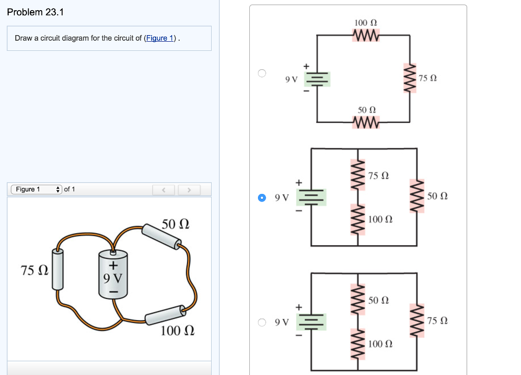
How To Draw Circuit Diagrams On Computer
28 Draw A Circuit Diagram For The Circuit Of (figure 1) . Wiring

How To Draw A Basic Circuit Diagram Circuit Diagram

Draw a circuit diagram for the circuit of (figure 1). AnswerData

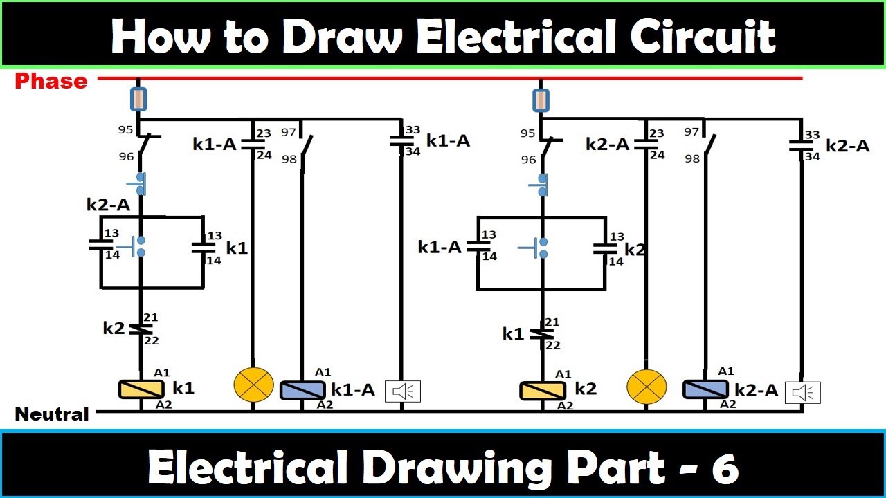
How To Draw Electrical Circuit Diagram
How To Write A Circuit Diagram
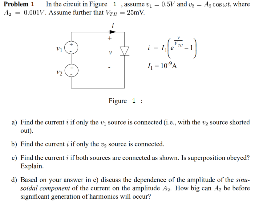
Solved Problem 1 In the circuit in Figure 1 , assume v1 =
3 Rules For Drawing Circuit Diagrams
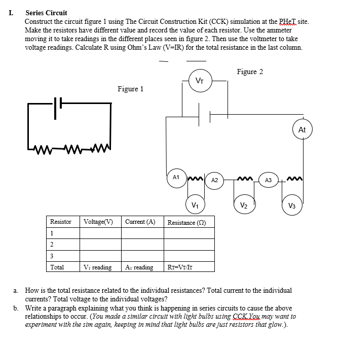
Solved I. Series Circuit Construct the circuit figure 1
Draw Schematic Diagram Of A Circuit
Web Calculations From Circuit Diagrams.
Inputs A And B Lead Into An And Gate With Output X.
A Student Builds The Circuit Below.
Web A Simple Circuit Contains The Minimum Amount Of Components That Allow It To Be A Functional Electric Circuit:
Related Post: