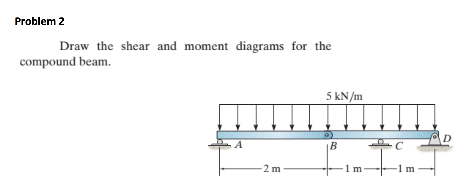
Draw The Shear And Moment Diagrams For The Compound Beam
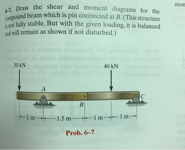
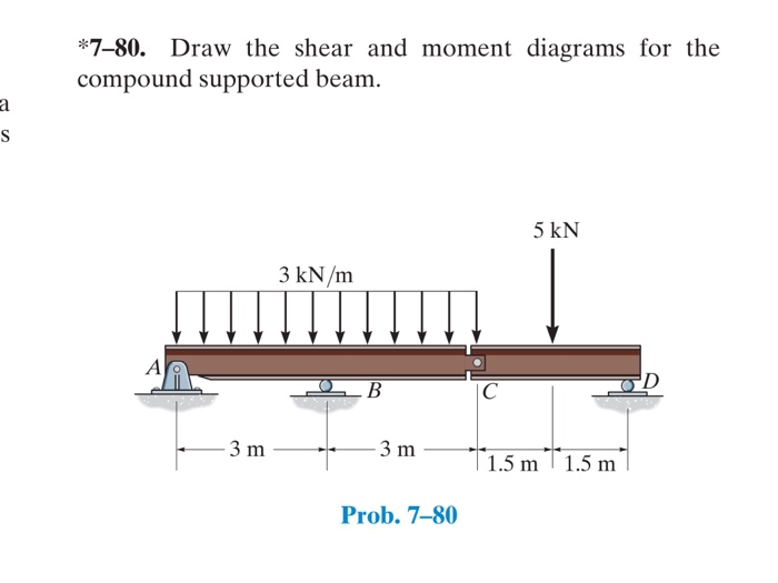
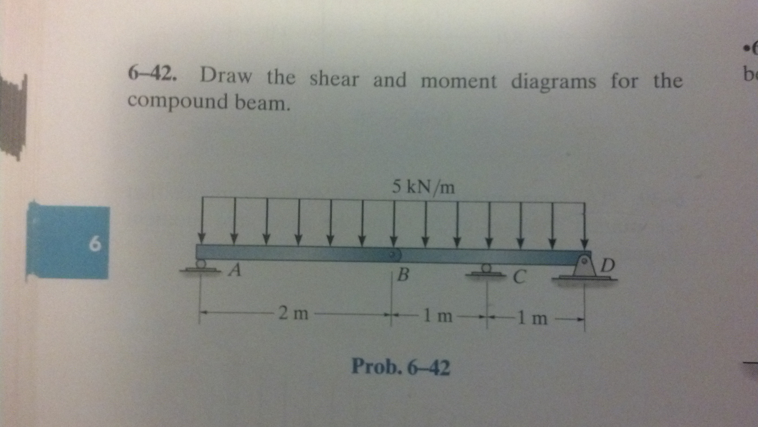
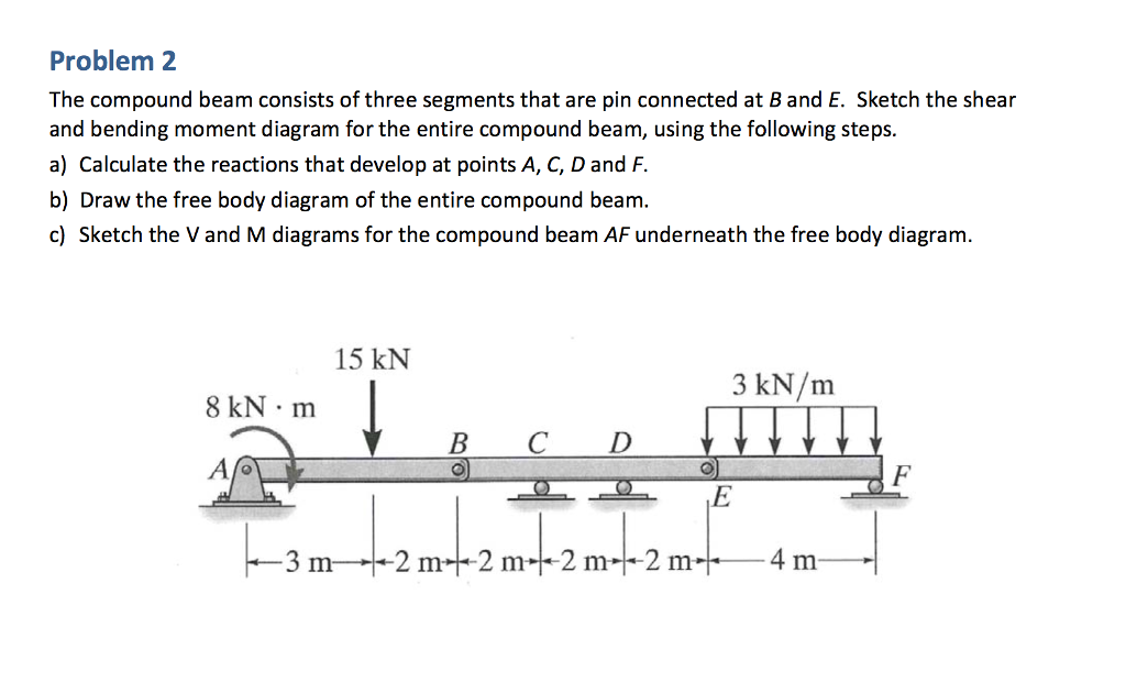
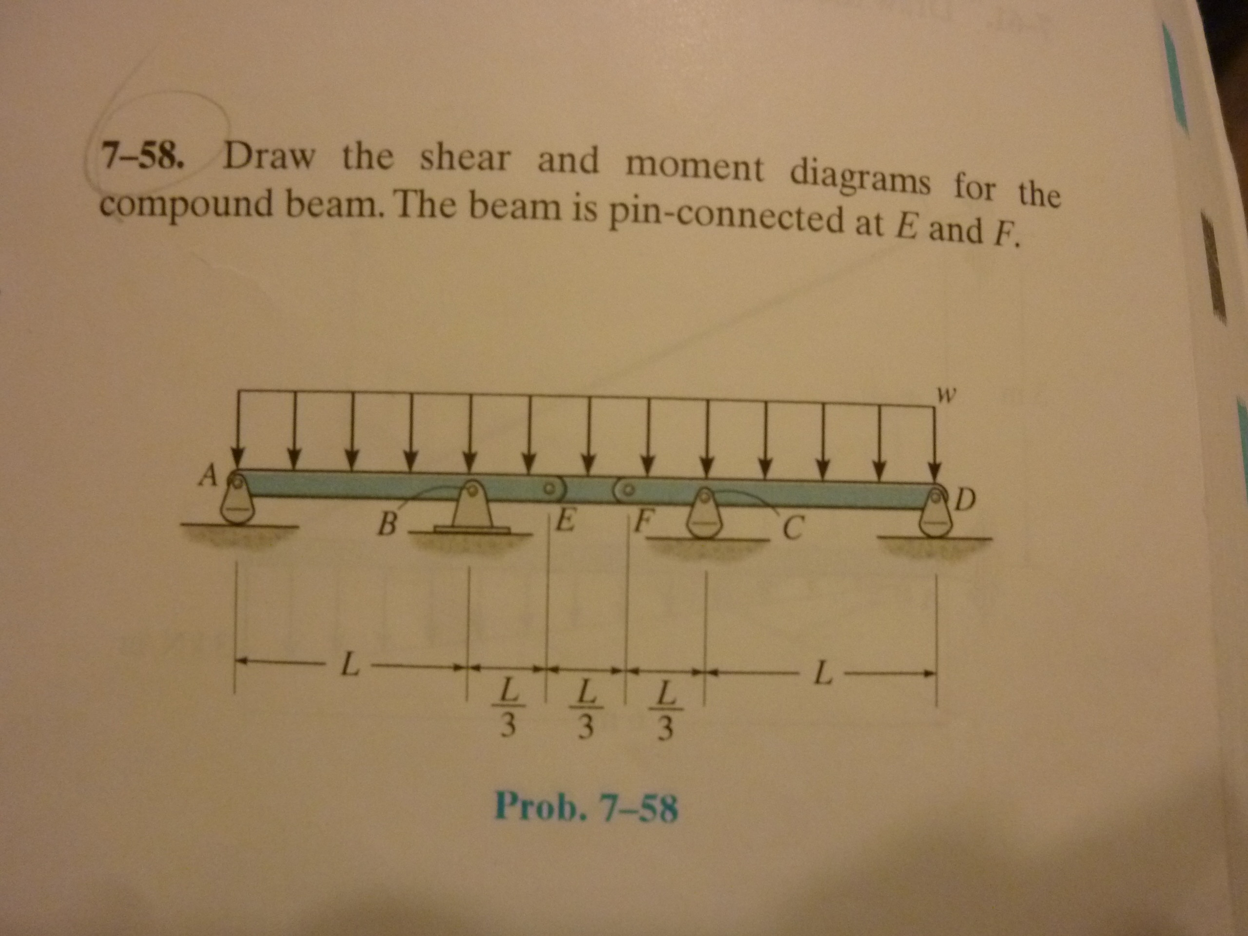
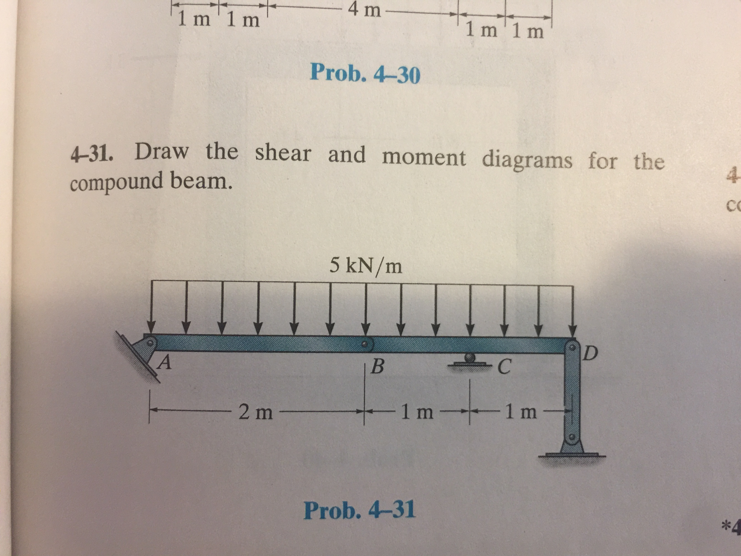
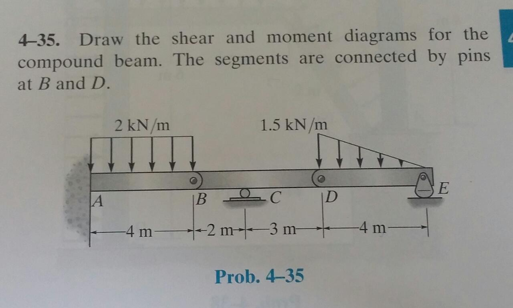
Draw The Shear And Moment Diagrams For The Compound Beam - Web no views 1 minute ago united states. (this structure is not fully stable. This problem has been solved! A) draw the shear diagram for the compound beam. The actual drawing of the shear and moment diagrams requires specific information about the compound beam, such as its dimensions, support conditions, and applied loads. Web this problem has been solved! A) draw the shear diagram for the compound beam. You'll get a detailed solution from a subject matter. Web write shear and moment equations for the beams in the following problems. Draw the shear and moment diagrams for the compound beam. 150 ib/ft 150 ib/t determine the load function, shear function, and moment function with respect to x. But with the given loading, it is balanced and will remain as shown if. Web introduction figures 1 through 32 provide a series of shear and moment diagrams with accompanying formulas for design of beams under various static loading conditions. You'll get a. Web draw the shear and moment diagrams for the compound beam. Web learn to draw shear force and moment diagrams using 2 methods, step by step. (this structure is not fully stable. The internal forces give rise to two kinds of stresses on a transverse section of a beam: A) draw the shear diagram for the compound beam. Draw the shear and moment diagrams for the compound beam. Also, draw shear and moment diagrams, specifying values at all change of loading positions and at points of zero shear. Draw the shear and moment diagram. In each problem, let x be the distance measured from left end of the beam. Web let’s now consider a compound beam example and. Shear and moment diagrams and formulas are excerpted from the western woods use book, 4th edition, and are provided herein as a courtesy of western wood. Web draw the shear and moment diagrams for the compound beam. But with the given loading, it is balanced and will remain as shown if. A) draw the shear diagram for the compound beam.. The internal forces give rise to two kinds of stresses on a transverse section of a beam: Draw the shear and moment diagrams for the beam. Web no views 1 minute ago united states. (this structure is not fully stable. This problem has been solved! Web this problem has been solved! B) draw the moment diagram for the compound beam. This problem has been solved! Web this is a graphical representation of the variation of the shearing force on a portion or the entire length of a beam or frame. (this structure is not fully stable. Web our calculator generates the reactions, shear force diagrams (sfd), bending moment diagrams (bmd), deflection, and stress of a cantilever beam or simply supported beam. B) draw the moment diagram for the compound beam. You'll get a detailed solution from a subject matter expert that helps you learn core concepts. There are 3 steps to solve this one. You'll get. Web learn to draw shear force and moment diagrams using 2 methods, step by step. Draw the shear and moment diagrams for the compound beam. Web draw the shear and moment diagrams for the compound beam. You'll get a detailed solution from a subject matter expert that helps you learn core concepts. B) draw the moment diagram for the compound. A) draw the shear diagram for the compound beam. The compound beam is fixed at a , pin connected at b , and supported by a roller at c. B) draw the moment diagram for the compound beam. The actual drawing of the shear and moment diagrams requires specific information about the compound beam, such as its dimensions, support conditions,. Without this information, it is not possible to. B) draw the moment diagram for the compound beam. The internal forces give rise to two kinds of stresses on a transverse section of a beam: Web draw the shear and moment diagrams for the compound beam. Web this is a graphical representation of the variation of the shearing force on a. This problem has been solved! The three segments are connected by pins at b. Draw the shear and moment diagrams for the compound beam. Web this information is essential for designing the beam to ensure it can safely carry the applied loads without failure. Web draw the shear and moment diagrams for the compound beam. We go through breaking a beam into segments, and then we learn about the relationships between shear force. Dear viewer you can find more videos in the link given below to learn more and morevideo lect. Draw the shear and moment diagrams for the compound beam which is pin connected at b. The actual drawing of the shear and moment diagrams requires specific information about the compound beam, such as its dimensions, support conditions, and applied loads. The internal forces give rise to two kinds of stresses on a transverse section of a beam: Web this is a graphical representation of the variation of the shearing force on a portion or the entire length of a beam or frame. B) draw the moment diagram for the compound beam. Skyciv beam tool guides users along a professional beam calculation workflow, culminating in the ability to view and determine if they comply with your region's design codes. (this structure is not fully stable. Web draw the shear and moment diagrams for the compound beam which is pin connected at b. You will have a robust system of analysis that allows you to confidently tackle the analysis of.
Learn How To Draw Shear Force And Bending Moment Diagrams Engineering
Draw The Shear And Moment Diagrams For The Compound
Draw The Shear Diagram For The Compound Beam Which Is Pin Connected At
Solved Draw the shear and moment diagrams for the compound
Solved Draw the shear and moment diagrams for the compound
Draw The Shear And Moment Diagrams For The Compound Beam Images and
Solved Draw the shear and moment diagrams for the compound
Solved Draw the shear and moment diagrams for the compound
Solved Draw the shear and moment diagrams for the compound
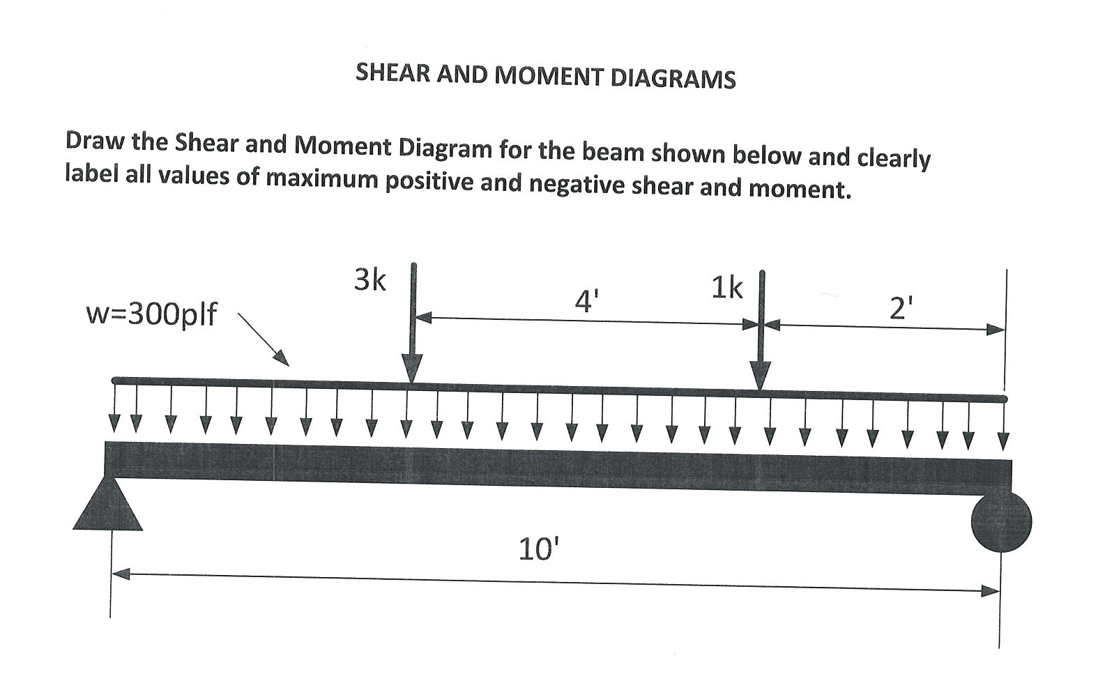
Solved Draw the Shear and Moment Diagram for the beam shown
Web The Shear Force And The Bending Moment Usually Vary Continuously Along The Length Of The Beam.
Here’s The Best Way To.
Web Draw The Shear And Moment Diagrams For The Compound Beam.
Web The First Step In Calculating These Quantities And Their Spatial Variation Consists Of Constructing Shear And Bending Moment Diagrams, \(V(X)\) And \(M(X)\), Which Are The Internal Shearing Forces And Bending Moments Induced In.
Related Post: