Drawing Machining Symbols
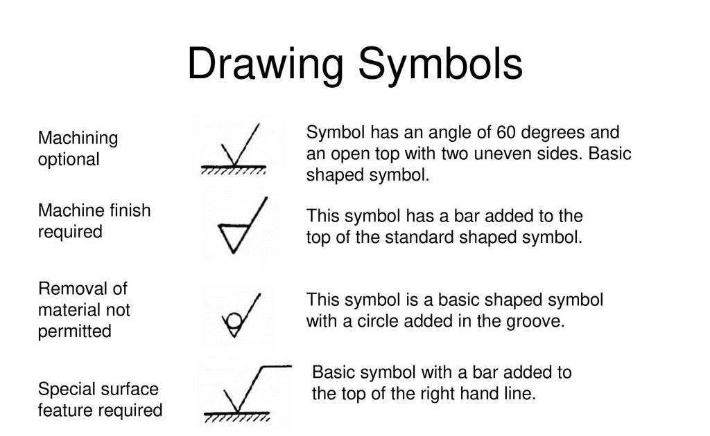
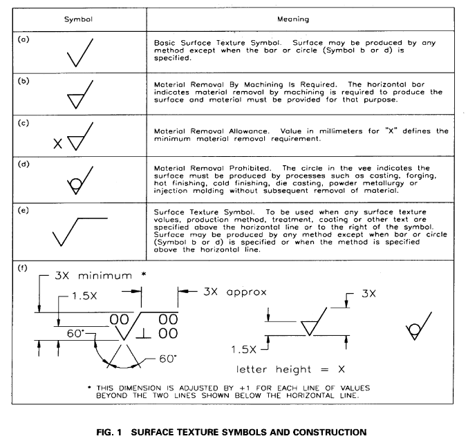
Drawing Machining Symbols - Mechanical drawing symbols — fluid power equipment library mechanical engineering solution offers 602 commonly used mechanical drawing symbols and objects which are professionally designed and grouped in 8 libraries: Asme also publishes the b41.6 surface texture standard, which contains definitions and measurement methods for. Web basic types of symbols used in engineering drawings are countersink, counterbore, spotface, depth, radius, and diameter. Dimensioning and tolerancing with 45 elements; You can also check out the gd&t symbols and terms on our site. Used when surface finish can be produced by any convenient technique. The following paragraphs cover the common terms most used in all aspects of machine drawings. Indicating a surface finish without removal of material (for example, quality of an initial casting). Engineers realize that absolute accuracy is impossible,. Symbols used for flat things. Here are more commonly used engineering drawing symbols and design elements as below. Web blueprint symbols, on the other hand, are a type of symbol used in technical drawings that represent various components and features of a project. The following paragraphs cover the common terms most used in all aspects of machine drawings. Web surface finish and surface roughness. You. Web engineering drawing abbreviations and symbols are used to communicate and detail the characteristics of an engineering drawing. Common symbols and notations in 2d drawings. Web machine drawing is a pictorial representation of machine or machine components or the part of a product which provides outline/inline detail of a product including how it is going to manufacture with certain rules.. Web basic types of symbols used in engineering drawings are countersink, counterbore, spotface, depth, radius, and diameter. Mechanical drawing symbols — fluid power equipment library mechanical engineering solution offers 602 commonly used mechanical drawing symbols and objects which are professionally designed and grouped in 8 libraries: Web the american society of mechanical engineers (asme) has published the y14.36m surface texture. Mechanical drawing symbols — fluid power equipment library mechanical engineering solution offers 602 commonly used mechanical drawing symbols and objects which are professionally designed and grouped in 8 libraries: Web to denote different surface finishes within different components, a list of surface finish symbols is required to reference contrasting finishes in a universally understood way. Dimensioning and tolerancing with 45. These symbols include circles, squares, triangles, and other shapes that provide information about the size, shape, and location of different components. Web mechanical engineering solution — 8 libraries are available with 602 commonly used mechanical drawing symbols in mechanical engineering solution, including libraries called bearings with 59 elements of roller and ball bearings, shafts, gears, hooks, springs, spindles and keys;. There are also specialty blueprint symbols associated with items such as welding or electronic components, but i will only be covering the standard blueprint symbols including those related to geometric dimensioning and tolerancing (gd&t). Symbols used to control angles. Engineers realize that absolute accuracy is impossible,. In learning to read machine drawings, you must first become familiar with the common. Web machine drawing is a pictorial representation of machine or machine components or the part of a product which provides outline/inline detail of a product including how it is going to manufacture with certain rules. Tolerance blocks display the general tolerances. Web mechanical engineering solution — 8 libraries are available with 602 commonly used mechanical drawing symbols in mechanical engineering. The following paragraphs cover the common terms most used in all aspects of machine drawings. Web surface finish and surface roughness. Web 1 clarity and conciseness engineering drawings often contain a large amount of information, including dimensions, tolerances, annotations, and other details. Web machine drawing is a pictorial representation of machine or machine components or the part of a product. Web symbols for roundness. Web the american society of mechanical engineers (asme) has published the y14.36m surface texture symbols standard, which illustrates the proper specification and use of surface texture symbols on technical drawings. This list includes abbreviations common to the vocabulary of people who work with engineering drawings in the manufacture and inspection of parts and assemblies. From basics. Here are more commonly used engineering drawing symbols and design elements as below. It depends on the structure of the metal before and after machining, depends on cutting conditions such as type and degree of sharpness of the cutting tool, depth of cut, amount of feed, coolant used, working conditions such as hot or cold, vibrations and. From basics to. In learning to read machine drawings, you must first become familiar with the common terms, symbols, and conventions defined and discussed in the following paragraphs. The following paragraphs cover the common terms most used in all aspects of machine drawings. Gd&t symbols that control location of a feature. Web surface finish and surface roughness. Web there are three symbols to represent the machining requirements. Web mechanical engineering solution — 8 libraries are available with 602 commonly used mechanical drawing symbols in mechanical engineering solution, including libraries called bearings with 59 elements of roller and ball bearings, shafts, gears, hooks, springs, spindles and keys; Web basic types of symbols used in engineering drawings are countersink, counterbore, spotface, depth, radius, and diameter. Complete guide to surface finish symbols, roughness charts, ra, rz, measurements, and callouts. Here are more commonly used engineering drawing symbols and design elements as below. Web learning to interpret these symbols is a significant part of understanding 2d drawings. See below for a full list of all surface finish symbols, their meaning, and how they should be applied: Web engineering drawing abbreviations and symbols are used to communicate and detail the characteristics of an engineering drawing. Whether you’re new to machining, want to figure out that never before seen drawing symbol, or simply need a refresher, this is your home to learn more about engineering drawings and. It depends on the structure of the metal before and after machining, depends on cutting conditions such as type and degree of sharpness of the cutting tool, depth of cut, amount of feed, coolant used, working conditions such as hot or cold, vibrations and. You can also check out the gd&t symbols and terms on our site. Symbols used to control angles.
MACHINING SYMBOL AND SURFACE TEXTURE YouTube

Engineering Drawing Symbols And Their Meanings Pdf at PaintingValley
Surface Finish Lay Symbols

Engineering Drawing Symbols And Their Meanings Pdf at PaintingValley

Mechanical Engineering Symbols And Their Meanings

Mechanical Drawing Symbols

Mechanical Engineering Drawing Symbols Pdf Free Download at

GD&T Symbols Reference Guide from Sigmetrix Mechanical design
Machine Drawing Symbols

16+ Machining Blueprint Symbols, Great!
Web A Wide Range Of Symbols Are Used To Create Engineering Drawings.
Web 1 Clarity And Conciseness Engineering Drawings Often Contain A Large Amount Of Information, Including Dimensions, Tolerances, Annotations, And Other Details.
Web This Surface Roughness Indication Method Pictorially Displays Information Such As The Surface Roughness Value, Cutoff Value, Sampling Length, Machining Method, Crease Direction Symbol, And Surface Waviness On The Surface Indication Symbol As Shown Below.
These Symbols Include Circles, Squares, Triangles, And Other Shapes That Provide Information About The Size, Shape, And Location Of Different Components.
Related Post: