Extension Line In Engineering Drawing
Extension Line In Engineering Drawing - These lines are drawn as thin, unbroken lines and should not touch the object being dimensioned. Extension lines are thin lines that are used to indicate the extent of a feature to which a dimension is attached. Web extension lines continue or extend from the surface of the object and establish the size of the dimension. An extension line is a thin line, You can set individual extension lines to display as centerline style. The extension line connects the object feature with the dimension line. Web extension lines on a drawing are fine, dark, solid lines that extend outward from a point on a drawing to which a dimension refers. Web the graphic feature represents a dimensional entity in a view or image of a drawing. Web how to draw dimension and extension lines in mechanical drawing arthur geometry 78.7k subscribers subscribe 1 1 view 4 minutes ago #geometry #howtodraw rules and typical mistakes to dimension. Visible gap — there should be a visible gap of 1 mm between the feature's corners and the end of the extension line. Dimension line arrowheads touch extension lines. Web an extension line extends a line on the object to the dimension line. They do not touch the object lines and extend slightly past the dimension line. Web how to draw dimension and extension lines in mechanical drawing arthur geometry 78.7k subscribers subscribe 1 1 view 4 minutes ago #geometry #howtodraw rules and. Extension lines are thin lines that are used to indicate the extent of a feature to which a dimension is attached. Sometimes, extension lines are used to demonstrate the extension of a surface to a theoretical intersection. They do not touch the object lines and extend slightly past the dimension line. The leader line should terminate in an arrowhead or. Web extension lines can be used to clarify which surfaces are to be considered, however is not necessary. Line characteristics, such as widths, breaks in the line, and zigzags, all have definite meanings. Web how to draw dimension and extension lines in mechanical drawing arthur geometry 78.7k subscribers subscribe 1 1 view 4 minutes ago #geometry #howtodraw rules and typical. Web extension lines are auxiliary lines to show which entity of the part or product is dimensioned with dimension lines and dimension values. Dimension line arrowheads touch extension lines. Line characteristics, such as widths, breaks in the line, and zigzags, all have definite meanings. They extend from the object line and terminate in a break or arrowhead, and are used. Line characteristics, such as widths, breaks in the line, and zigzags, all have definite meanings. Web extension lines thin lines used to establish the extent of a dimension. This type is also used to draw outlines of adjacent and revolved sections. Extension lines are solid and thin lines like dimension lines. Web how to draw dimension and extension lines in. (b) dimension lines show the direction and extent of dimension. The leader line should terminate in an arrowhead or dot. Dimension lines are thin and are used to show the actual size of an object. Web how to draw dimension and extension lines in mechanical drawing arthur geometry 78.7k subscribers subscribe 1 1 view 4 minutes ago #geometry #howtodraw rules. The extension line connects the object feature with the dimension line. Leader lines thin lines used to connect a specific note to a feature. Web the extension lines for dimensioning should run from the outlines without leaving a gap and extend beyond the dimension lines. Extension lines provide a means of displaying a measurement without placing the dimension on the. Extension lines are also thin lines, showing the limits of dimensions. An extension line is a thin line, These thick, solid lines show the visible edges, corners, and surfaces of a part. Extension lines are solid and thin lines like dimension lines. Web extension lines help define the specific area or section to which the dimension applies, ensuring clarity and. Sometimes, extension lines are used to demonstrate the extension of a surface to a theoretical intersection. These lines are drawn as thin, unbroken lines and should not touch the object being dimensioned. Extension lines are also thin lines, showing the limits of dimensions. An extension line is a thin line, Web the graphic feature represents a dimensional entity in a. An extension line is a thin line, Feature’s corners and the end of the extension line. Web extension lines on a drawing are fine, dark, solid lines that extend outward from a point on a drawing to which a dimension refers. Web line conventions by manufacturinget.org · july 28, 2011 line types (see also asme y14.2m) when you are preparing. Sometimes, extension lines are used to demonstrate the extension of a surface to a theoretical intersection. Object lines stand out on the drawing and clearly define the outline and features of the object. The first dimension line should be approximately 12 mm (0.6 in) from the object. Web engineering lines are graphical representations used in technical drawings to communicate information about the shape, size, and features of objects. Type c limits or boundaries of partial or interrupted views Dimension lines are thin and are used to show the actual size of an object. Usually, the dimension line meets the extension line at right angles. Sometimes, leaders are used in place of extension and dimension lines, especially when dimensioning arcs and circles. Web extension lines are auxiliary lines to show which entity of the part or product is dimensioned with dimension lines and dimension values. Extension lines are thin lines that are used to indicate the extent of a feature to which a dimension is attached. They should not cross dimension lines. Web extension lines continue or extend from the surface of the object and establish the size of the dimension. (c) leader lines are used to direct an expression, in note form, to the intended place on the drawing. In the 2009 standard, this symbol cannot be applied to a surface in this manner. This lets you identify when an extension line. On the end opposite the arrow, the leader line will have a short, horizontal shoulder.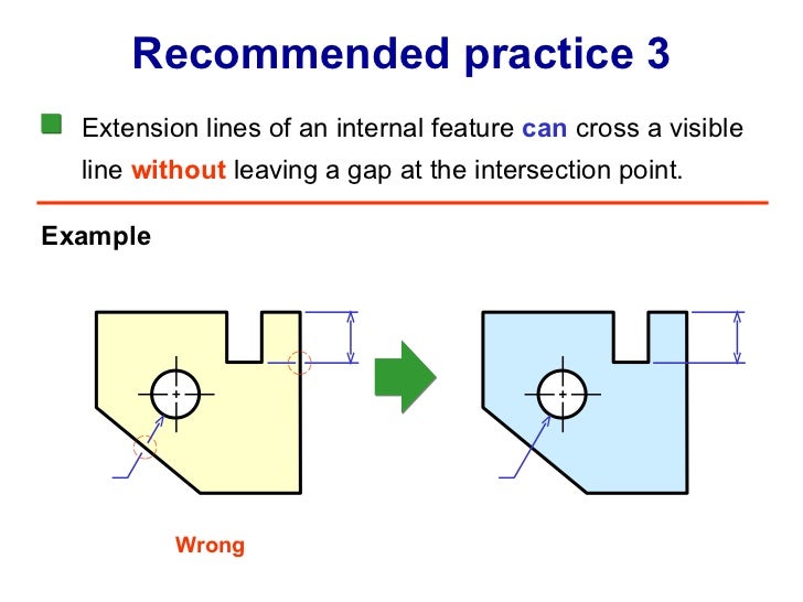
Extension Line In Engineering Drawing
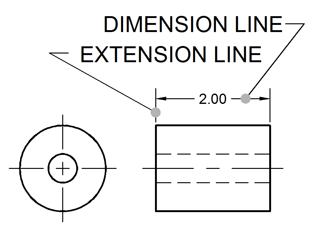
Dimension and Extension Lines ToolNotes
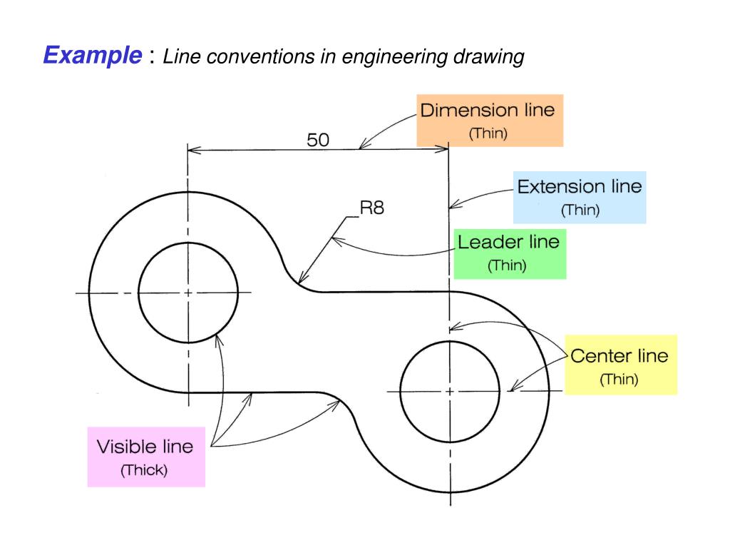
Extension Line In Engineering Drawing

Engineering Drawing Chapter 07 dimensioning

Extension Lines YouTube

Dimensioning Basic Blueprint Reading
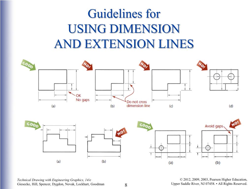
Extension Line In Engineering Drawing
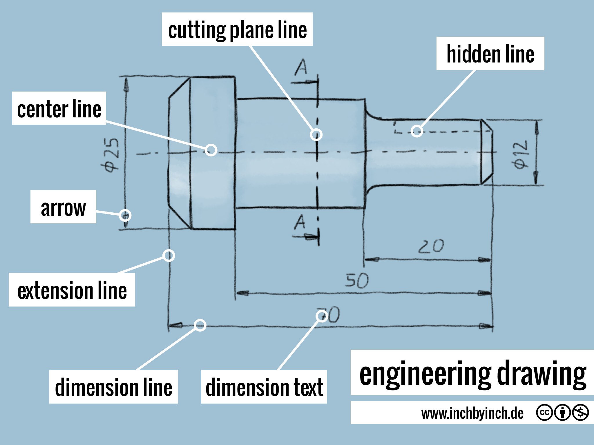
INCH Technical English engineering drawing

PPT A Brief Introduction to Engineering Graphics PowerPoint

Manipulating SOLIDWORKS Extension Lines in your Drawings
Text Is Extended From This Shoulder Such That The Text Height Is Centered With The Shoulder Line.
Web Object Lines (Figure 3) Are The Most Common Lines Used In Drawings.
The Leader Line Should Terminate In An Arrowhead Or Dot.
They Extend From The Object Line And Terminate In A Break Or Arrowhead, And Are Used To Guide The Dimension Line.
Related Post: