Hidden Line In Engineering Drawing
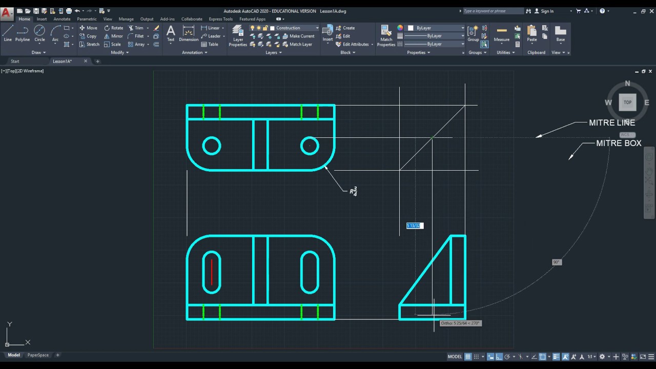
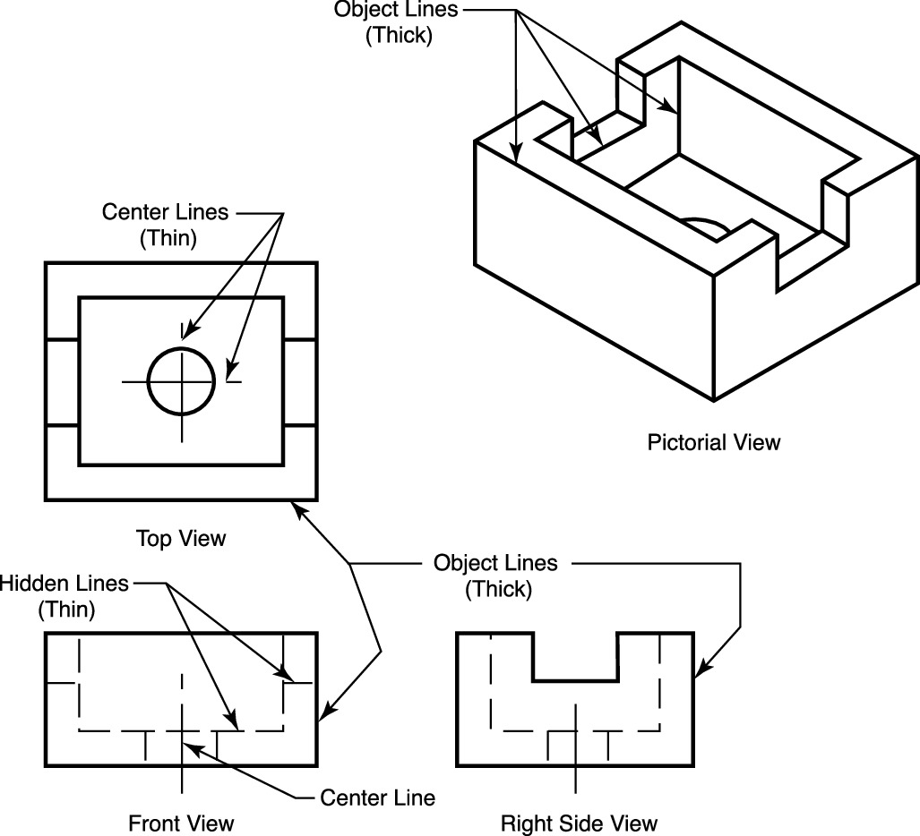
Hidden Line In Engineering Drawing - Web hidden lines are used in engineering drawings to represent features that cannot be seen in a particular view but are necessary to fully define the part or assembly. Hidden features should be omitted in all areas of a. Extension lines can annotate an area that is being. Figure 3.46 shows a case in which hidden lines are needed because a projecting part cannot be clearly shown without them. Web object lines stand out on the drawing and clearly define the outline and features of the object. Center lines center lines are used to indicate the center of symmetrical objects or the center axis of cylindrical or circular shapes. For example, the length of an internal step of a part may be shown using hidden lines. Sometimes they are used to make a drawing easier to understand. A section lined area is always completely bounded by a visible outline. Web a hidden line, also known as a hidden object line is a medium weight line, made of short dashes about 1/8” long with 1/16”gaps, to show edges, surfaces and corners which cannot be seen. The section lines in all areas should be parallel. Hidden lines are light, dashed, narrow, and short. They are dark and thick lines of any engineering design drawing. Are used to show the center of holes and symmetrical features. Hidden lines show edges and contours of important features that are obscured by the geometry of the part. Web in an engineering drawing, visible lines are the thick, solid lines that represent the visible edges and boundaries of an object or part. Hidden lines are omitted from pictorial drawings unless they are needed to make the drawing clear. For example, the length of an internal step of a part may be shown using hidden lines. Engineering drawings use. In other words, a primary reason for creating a section view is the elimination of hidden lines. Hidden lines, as you already know, are used to represent features that cannot be seen in the current view. A section lined area is always completely bounded by a visible outline. They are drawn as short dashes that are equally spaced. Are used. Web types of lines for technical drawings visible lines. A section lined area is always completely bounded by a visible outline. Figure 3.46 shows a case in which hidden lines are needed because a projecting part cannot be clearly shown without them. The dashed line may be either thick or thin, but only one type (thick or thin) should be. Center lines center lines are used to indicate the center of symmetrical objects or the center axis of cylindrical or circular shapes. Hidden lines, as you already know, are used to represent features that cannot be seen in the current view. Hidden lines are omitted from pictorial drawings unless they are needed to make the drawing clear. As in all. It helps to show points that would not be otherwise visible on the drawing. They are dark and thick lines of any engineering design drawing. Their purpose is to clearly and accurately depict the shape and size of the object, as well as to distinguish it from any. These lines are drawn as thin, evenly spaced dashes. Web 18.06.2020 by. Web in an engineering drawing, visible lines are the thick, solid lines that represent the visible edges and boundaries of an object or part. Hidden lines, as you already know, are used to represent features that cannot be seen in the current view. Thin chain line the thin chain line is used to indicate center lines, the lines of symmetry. Center lines center lines are used to indicate the center of symmetrical objects or the center axis of cylindrical or circular shapes. A section lined area is always completely bounded by a visible outline. Web in an engineering drawing, visible lines are the thick, solid lines that represent the visible edges and boundaries of an object or part. As in. Web the dashed line is used to indicate hidden details like hidden outlines and hidden edges. A common use is to specify the geometry necessary for the construction of a component and is called a detail drawing. A surface or edge that is shown in one view with. Hidden lines are light, dashed, narrow, and short. The purpose is to. A section lined area is always completely bounded by a visible outline. Hidden lines (figure 4) are used to show edges and surfaces that are not visible in a view. Web it is frequently used for symmetrical objects. The dashed line may be either thick or thin, but only one type (thick or thin) should be used on a single. Center lines center lines are used to indicate the center of symmetrical objects or the center axis of cylindrical or circular shapes. A section lined area is always completely bounded by a visible outline. The dashed line may be either thick or thin, but only one type (thick or thin) should be used on a single drawing or set of drawings. Cutting plane lines are used in section drawings to. Also known as object lines, visible. Hidden lines show edges and contours of important features that are obscured by the geometry of the part. Web hidden lines are used in engineering drawings to represent features that cannot be seen in a particular view but are necessary to fully define the part or assembly. Web hidden lines in a drawing represent the edges where surfaces meet but are not directly visible. They are drawn as short dashes that are equally spaced. This animated video details and showcases their use, purpose and advantages &. For example, the length of an internal step of a part may be shown using hidden lines. Web object lines stand out on the drawing and clearly define the outline and features of the object. They are dark and thick lines of any engineering design drawing. Web the hidden line is another type of line used in mechanical drawing. It helps to show points that would not be otherwise visible on the drawing. Thin chain line the thin chain line is used to indicate center lines, the lines of symmetry and also trajectories.
Do you use hidden lines in perspective and isometric drawings? r

Types of Lines in Engineering Drawing/ Hidden line and OutlinePart 1
2020 Drawing Hidden Lines for an Orthographic drawing using alignment

Engineering Drawing Hidden Lines for Info TECHNOLOGY and INFORMATION

Type of Line used in (ED) Engineering Drawing Phantom line hidden
Quick Reference For Using Technical Drawings Scroll Saw Woodworking

How to show ug nx 8 drafting hidden lines in drawing YouTube
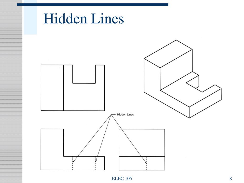
PPT Engineering Drawing PowerPoint Presentation, free download ID

Hidden Lines YouTube

ENGR 1304 Ch2 Views and Perspectives
Extension Lines Can Annotate An Area That Is Being.
Hidden Features Should Be Omitted In All Areas Of A.
Web Types Of Lines For Technical Drawings Visible Lines.
They Are Typically Represented Using Short Dashes Or Dotted Lines.
Related Post: