Isometric Drawing Symbols For Piping
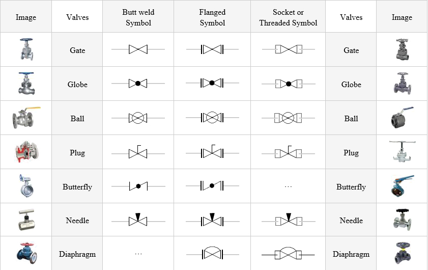
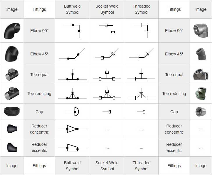
Isometric Drawing Symbols For Piping - Isometric views can be identified by their characteristic lines and angles. Web but still some questions remain: The iso, as isometric are commonly referred, is oriented on the grid relative to the north arrow found on plan drawings. Isometric symbols for fittings, flanges, and. Isometric drawings are typically used to show the details of a piping system, such as the size and type of piping, the direction of flow of the fluids, and the location of valves, pumps, and other equipment nozzles. The user can use an isometric projection template to help place the shapes at the right angles. Piping fabrication work is based on isometric drawings. Section of left or right of piping isometric drawing includes: This section delves into how to interpret and deduce flow direction from isometric drawings: Web piping isometric drawing software is an essential tool for piping engineers and designers to create detailed isometric drawings of piping systems. Familiarize yourself with these symbols for better comprehension. Section of left or right of piping isometric drawing includes: Web piping symbols serve as the alphabet of isometric drawings, with each symbol representing a specific component, similar to words in a language. Piping isometric symbols and conventions are employed to depict different components of pipeline systems, such as valves, fittings, and. Piping isometric symbols and conventions are employed to depict different components of pipeline systems, such as valves, fittings, and connections. Web but still some questions remain: Web piping isometric drawing is an isometric representation of single pipe line in a plant. Familiarize yourself with these symbols for better comprehension. Web understanding flow direction. Checkout list of such symbols given below. This video shows isometric drawing symbols for various types of valves such as gate valves, globe valves, check valves, butterfly valves, diaphragm. Piping isometric drawing consists of three sections. Web understanding flow direction. Isometric views can be identified by their characteristic lines and angles. Fittings, flanges, and valves play essential roles in pipeline isometric drawings, each with unique symbols according to iso standards. Web understanding flow direction. Symbols are shown in black lines. Usually, piping isometrics are drawn on preprinted paper, with lines of equilateral triangles form of 60°. Web use of piping symbols: Checkout list of such symbols given below. The user can use an isometric projection template to help place the shapes at the right angles. Isometrics are also drawn as a schematic, which means they are not drawn to scale. Web piping isometric drawing is an isometric representation of single pipe line in a plant. Flow direction is a critical aspect. Web but still some questions remain: A piping isometric drawing is a technical drawing that depicts a pipe spool or a complete pipeline using an isometric representation. Familiarize yourself with these symbols for better comprehension. Web use of piping symbols: Besides the common shapes, such as the square, excel lets users create their own shapes using the freeform shape feature. Web accurate drawing symbols, callouts, precise coordinates, and elevations provide intricate information to the fabricator. All of our vector cad models are of the highest quality. The drawing axes of the isometrics intersect at an angle of 60°. Web but still some questions remain: Web the isometric must provide a detailed description of the pipe’s routing from beginning to end. Flow direction is a critical aspect of piping systems. Various symbols are used to indicate piping components, instrumentation, equipments in engineering drawings such as piping and instrumentation diagram (p&id), isometric drawings, plot plan, equipment layout, welding drawings etc. The drawing axes of the isometrics intersect at an angle of 60°. Isometric views can be identified by their characteristic lines and. Usually, piping isometrics are drawn on preprinted paper, with lines of equilateral triangles form of 60°. Web piping isometric drawing symbols for various markings. The use of coordinate and elevation callouts to determine configuration dimensions of the routed pipe is explained. Weld joint type and its location; Section of left or right of piping isometric drawing includes: Web the isometric must provide a detailed description of the pipe’s routing from beginning to end. Web isometric drawing symbols for piping valves. All of our vector cad models are of the highest quality. Web the main body of a piping isometric drawing is consist of: Isometric views can be identified by their characteristic lines and angles. Web isometric drawing symbols for piping valves. Section of left or right of piping isometric drawing includes: Fittings, flanges, and valves play essential roles in pipeline isometric drawings, each with unique symbols according to iso standards. Symbols are shown in black lines. The iso, as isometric are commonly referred, is oriented on the grid relative to the north arrow found on plan drawings. Web description piping isometric dwg symbols designed just for you in autocad. Familiarize yourself with these symbols for better comprehension. Web the symbols that represent fittings, valves and flanges are modified to adapt to the isometric grid. It is the most important deliverable of piping engineering department. Web isometric drawing symbols for piping fittings. Checkout list of such symbols given below. This section delves into how to interpret and deduce flow direction from isometric drawings: Web piping isometric drawing is an isometric representation of single pipe line in a plant. Web 0:00 / 5:44 how to read piping isometric drawing symbols. Isometric drawings are typically used to show the details of a piping system, such as the size and type of piping, the direction of flow of the fluids, and the location of valves, pumps, and other equipment nozzles. These tools generate the 3d representation of the piping layout, including pipe dimensions, fittings,.
How to read isometric drawing piping dadver

Piping Isometric Drawing Symbols Pdf at Explore

Piping Coordination System Mechanical symbols for Isometric drawings
Pipe sketch pipeline isometric drawing symbols nelocraft

What is Piping Isometric drawing? How to Read Piping Drawing? ALL

PIPE FITTING ISOMETRIC Free CAD Block Symbols And CAD Drawing
Piping Coordination System Mechanical symbols for Isometric drawings

Piping Isometric Drawings The Piping Engineering World

Basic Piping Isometric Symbols Piping Analysis YouTube

Piping Design Basics Piping Isometric Drawings Piping Isometrics
Besides The Common Shapes, Such As The Square, Excel Lets Users Create Their Own Shapes Using The Freeform Shape Feature.
Web An Isometric Drawing Is A Type Of Pictorial Drawing In Which Three Sides Of An Object Can Be Seen In One View.
Web Understanding Flow Direction.
The Use Of Coordinate And Elevation Callouts To Determine Configuration Dimensions Of The Routed Pipe Is Explained.
Related Post: