Line Types Engineering Drawing
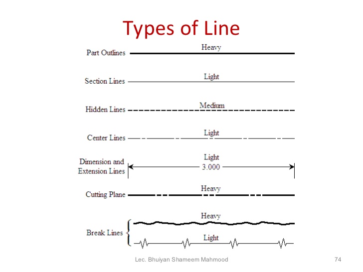
Line Types Engineering Drawing - Web following are the different types of lines used in engineering drawing: Various symbols, line types, notations, and patterns in the engineering drawings. Special thanks to filmorago app for editing of this video. Web 18.06.2020 by andreas velling engineering drawing basics explained an engineering drawing is a subcategory of technical drawings. Web different types of lines in engineering drawing introduction to lines in engineering drawing. This line is used to represent the edges of objects, such as a part or a surface. Continues wide lines solid lines are dark and thick lines that are prominent and clearly visible. To represent symmetry, to represent paths of motion, to mark the centers of circles and the axes of symmetrical parts, such as cylinders and bolts. Lines in engineering drawing are more than just strokes on paper; There are different subcategories of visible lines: They are dark and thick lines of any engineering design drawing. Web published by gayamadhusanka on july 8, 2023 engineering drawings are some kind of language to represent the engineer’s ideas. • outlines • hidkt~t:11 lines • leader' lines • cell1;tr.e lines • dim:ret:1sion lines • break lines • crives hatching lines completiot:11 guidance the work may meed to be. When considering the lines, there are different types of lines in engineering drawing. Web this video explains about different line types like thick, thin, dash, chain line etc with relevant application in engineering drawing. Web it is important to understand what each line type is and what they mean. Special thanks to filmorago app for editing of this video. There. They represent the visible edges, boundaries, and outlines of objects. These are aligned and unidirectional. Object lines (figure 3) are the most common lines used in drawings. Web different line types used on engineering drawings. Web types of lines in engineering drawing: A quiz completes the activity. Visible lines visible lines are the most fundamental type of lines used in engineering drawings. Mastering different types of lines in engineering drawing. These are aligned and unidirectional. Also known as object lines, visible. A variety of line styles graphically represent physical objects, including visible, hidden, center, cutting plane, section, and phantom. Lines in engineering drawing are more than just strokes on paper; Indicates the edge is behind a face; Web types of lines for technical drawings visible lines. These are aligned and unidirectional. The purpose is to convey all the information necessary for manufacturing a product or a part. These are mainly used to indicate the edges of components and the boundaries of areas on the component. There are two main types of dimensioning. Each style can be divided into different types. The continuous thick line is used to show visible outlines or. They represent the visible edges, boundaries, and outlines of objects. Web the standard line types used in technical drawings are center lines are used: Object lines stand out on the drawing and clearly define the outline and features of the object. They are dark and thick lines of any engineering design drawing. Putting the line types, line weights and line. In the world of engineering, precision is paramount. Web types of lines for technical drawings visible lines. Web basic types of lines used in engineering drawings by kelly curran glenn sokolowski in this highly interactive object, learners associate basic line types and terms with engineering drawing geometry. These are aligned and unidirectional. There are three types of lines: When considering the lines, there are different types of lines in engineering drawing. To represent symmetry, to represent paths of motion, to mark the centers of circles and the axes of symmetrical parts, such as cylinders and bolts. Special thanks to filmorago app for editing of this video. Break lines are used to show where an object is broken to. The purpose is to convey all the information necessary for manufacturing a product or a part. Object lines (figure 3) are the most common lines used in drawings. Web d identif~liilre types used on engineering drawings. Web 18.06.2020 by andreas velling engineering drawing basics explained an engineering drawing is a subcategory of technical drawings. In the world of engineering, precision. They provide features that can not be seen in a. Continues wide lines solid lines are dark and thick lines that are prominent and clearly visible. A variety of line styles graphically represent physical objects, including visible, hidden, center, cutting plane, section, and phantom. Web types of lines in engineering drawing: The purpose is to convey all the information necessary for manufacturing a product or a part. Usually, a number of drawings are necessary to completely specify even a simple component. Engineering drawings use standardised language and symbols. Break lines are used to show where an object is broken to save drawing space or reveal interior features. Hidden lines are light, dashed, narrow, and short. Aligned dimensioning is the most common type of dimensioning used in engineering drawing. They are dark and thick lines of any engineering design drawing. Putting the line types, line weights and line type scales together, we get the. These thick, solid lines show the visible edges, corners, and surfaces of a part. Various symbols, line types, notations, and patterns in the engineering drawings. They represent the visible edges, boundaries, and outlines of objects. Web basic types of lines used in engineering drawings by kelly curran glenn sokolowski in this highly interactive object, learners associate basic line types and terms with engineering drawing geometry.
INCH Technical English pictorial engineering drawing line types

10 Different Types of Lines Used In Engineering Drawing
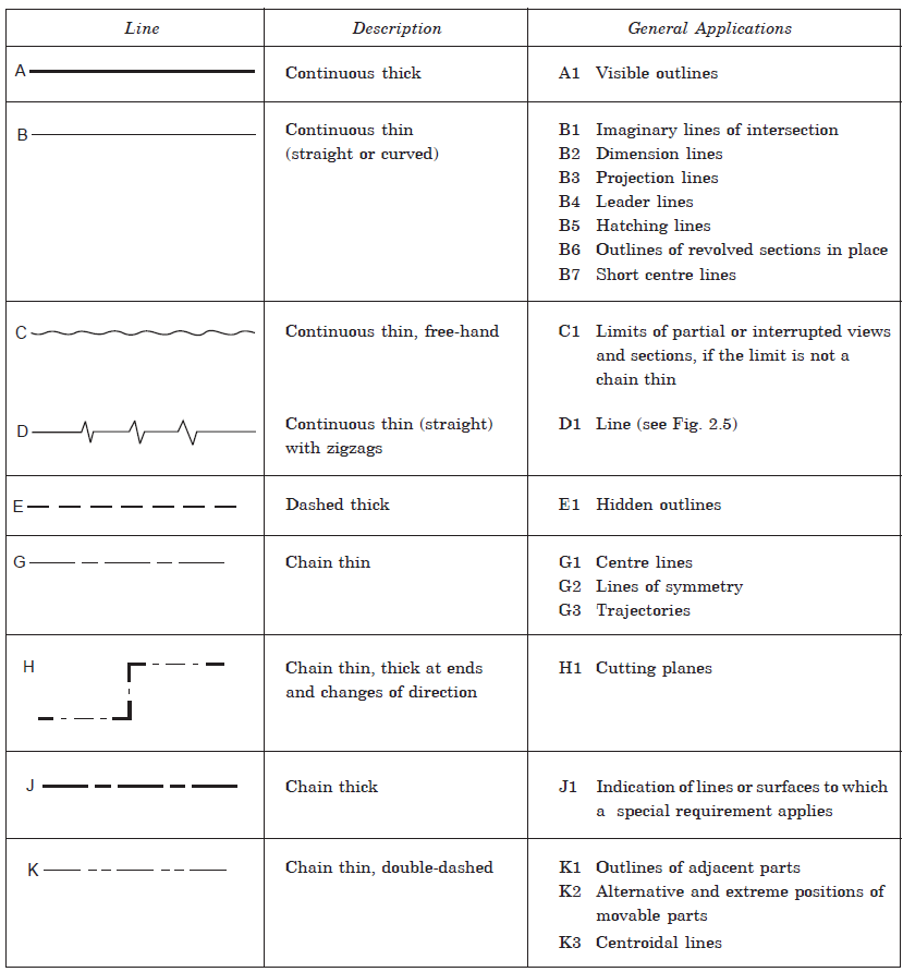
ENGINEERING DRAWING Lines
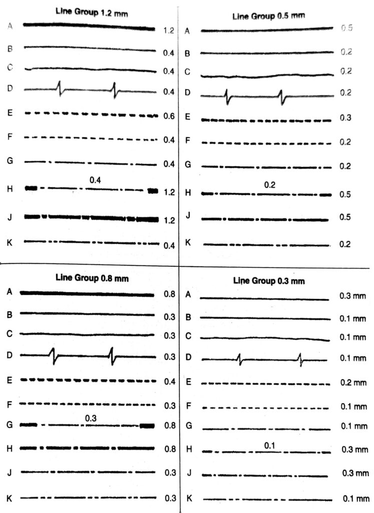
ENGINEERING DRAWING Lines
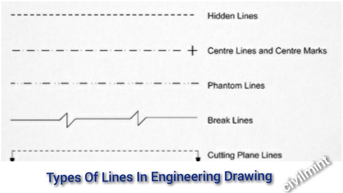
Types Of Lines In Engineering Drawing

Different Types of LINES in Engineering Drawing//Classification of

10 Different Types of Lines Used In Engineering Drawing

What are Lines & Types Of Lines in Engineering Drawing ? YouTube
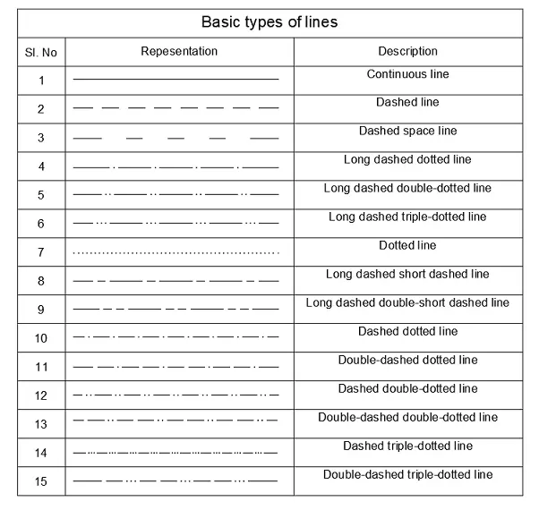
Types Of Line In Engineering No.1 Detailed Guide To Line Types
Engineering Drawing 8 Tips to Improve Engineering Drawing Skills
These Are Aligned And Unidirectional.
Each Style Can Be Divided Into Different Types.
To Represent Symmetry, To Represent Paths Of Motion, To Mark The Centers Of Circles And The Axes Of Symmetrical Parts, Such As Cylinders And Bolts.
These Are Mainly Used To Indicate The Edges Of Components And The Boundaries Of Areas On The Component.
Related Post: