Machine Drawing Symbols
Machine Drawing Symbols - Construction 53 what are machinist blueprint symbols? Name and address of the company or agency who prepared or owns the drawing. Web how to read machine drawings? Web slide 1 machine drawing. Understand and apply surface finish and welding symbols. In some cases, there is no standard symbol for a material or piece of equipment. Here are more commonly used engineering drawing symbols and design elements as below. The symbols covered in on the following pages are an example of the widespread use of symbols and abbreviations in industry. There are other information blocks like it, but the title block serves as the context in which the drawing should be perceived. Select proper symbols for mechanical components. 1.1 symbols permit consistency in the way dimensions and tolerances are specified, and each symbol has a clearly defined meaning. Web this chapter contains symbolic representation of different commonly used mechanical components for assembly drawing work. Web a wide range of symbols are used to create engineering drawings. A feature control symbol is made of geometric symbols and tolerances. Understanding. Mechanical drawing symbols — fluid power equipment library mechanical engineering solution offers 602 commonly used mechanical drawing symbols and objects which are professionally designed and grouped in 8 libraries: You can also check out the gd&t symbols and terms on our site. The basic symbol types used in engineering drawings are diameter, depth, radius, counterbore, spotface, and countersink. Fillets and. Interpret the machine components and conventions used in the drawing. Web engineering drawing abbreviations and symbols are used to communicate and detail the characteristics of an engineering drawing. After reading the chapter you will be able to. There are also specialty blueprint symbols associated with items such as welding or electronic components, but i will only be covering the standard. 1.1 symbols permit consistency in the way dimensions and tolerances are specified, and each symbol has a clearly defined meaning. Web 1 clarity and conciseness engineering drawings often contain a large amount of information, including dimensions, tolerances, annotations, and other details. Assemble machine components through drawings. Web check out our full list of machining blueprint symbols to help you figure. Web engineering drawing abbreviations and symbols are used to communicate and detail the characteristics of an engineering drawing. Web this chapter contains symbolic representation of different commonly used mechanical components for assembly drawing work. Web basic and common symbols. See the symbols types of tolerances an introduction to the different types of blueprint tolerances you will encounter with plenty of. There are also specialty blueprint symbols associated with items such as welding or electronic components, but i will only be covering the standard blueprint symbols including those related to geometric dimensioning and tolerancing (gd&t). Construction 53 what are machinist blueprint symbols? Machine drawings employ standardized symbols and conventions to represent various features, materials, and processes. Fillets and rounds fillets are. Pictures of each symbol included. Assemble machine components through drawings. Engineering drawing is a fundamental skill in many branches of engineering, including mechanical, electrical, and civil engineering. Web mechanical engineering solution — 8 libraries are available with 602 commonly used mechanical drawing symbols in mechanical engineering solution, including libraries called bearings with 59 elements of roller and ball bearings, shafts,. This list includes abbreviations common to the vocabulary of people who work with engineering drawings in the manufacture and inspection of parts and assemblies. Engineering drawing is a fundamental skill in many branches of engineering, including mechanical, electrical, and civil engineering. Mechanical drawing symbols — fluid power equipment library mechanical engineering solution offers 602 commonly used mechanical drawing symbols and. Mechanical engineering solution — 8 libraries are available with 602 commonly used mechanical drawing symbols in mechanical engineering solution, including libraries called bearings with 59 elements of roller and ball bearings, shafts, gears, hooks, springs, spindles and keys; This list includes abbreviations common to the vocabulary of people who work with engineering drawings in the manufacture and inspection of parts. Understanding these symbols is essential for. The basic symbol types used in engineering drawings are diameter, depth, radius, counterbore, spotface, and countersink. Interpret the components such as fasteners, riveted joints, welded joints and keys. Construction 53 what are machinist blueprint symbols? There are other information blocks like it, but the title block serves as the context in which the drawing. Web basic and common symbols. Web mechanical engineering solution — 8 libraries are available with 602 commonly used mechanical drawing symbols in mechanical engineering solution, including libraries called bearings with 59 elements of roller and ball bearings, shafts, gears, hooks, springs, spindles and keys; Understanding these symbols is essential for. Mechanical drawing symbols — fluid power equipment library mechanical engineering solution offers 602 commonly used mechanical drawing symbols and objects which are professionally designed and grouped in 8 libraries: 1.1 symbols permit consistency in the way dimensions and tolerances are specified, and each symbol has a clearly defined meaning. Web a wide range of symbols are used to create engineering drawings. The basic symbol types used in engineering drawings are diameter, depth, radius, counterbore, spotface, and countersink. Unlike a model, engineering drawings offer more specific detail and requirements, such as: The size and orientation of each shape may have specific meanings in the context of the overall diagram. There are also specialty blueprint symbols associated with items such as welding or electronic components, but i will only be covering the standard blueprint symbols including those related to geometric dimensioning and tolerancing (gd&t). You can also check out the gd&t symbols and terms on our site. Web mechanical drawing symbols are used to represent different components in a mechanical system. See the symbols types of tolerances an introduction to the different types of blueprint tolerances you will encounter with plenty of examples to make them easy to understand. The symbols and abbreviations covered in this module relate to a few trades and professions. Using abbreviations and symbols allows for concise representation, making the drawings easier to read and understand. Web this chapter contains symbolic representation of different commonly used mechanical components for assembly drawing work.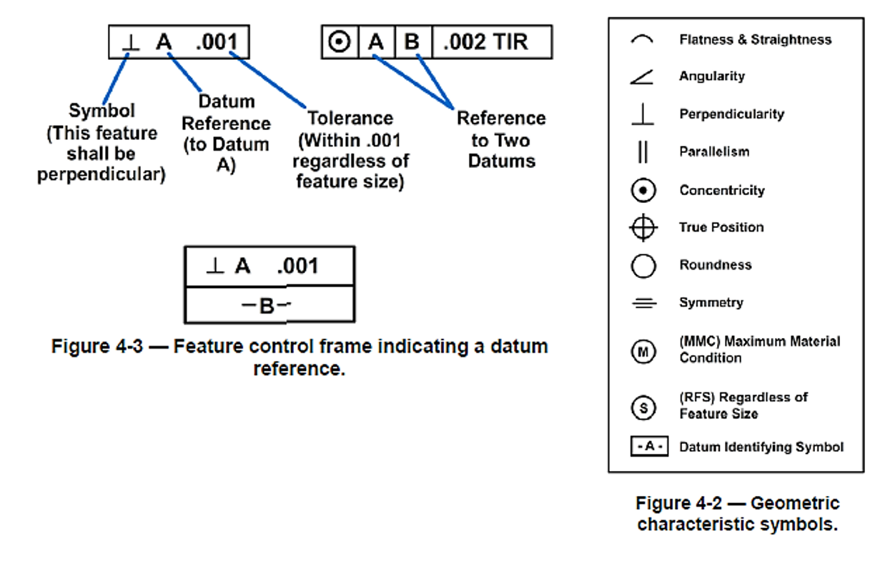
MACHINE DRAWINGS

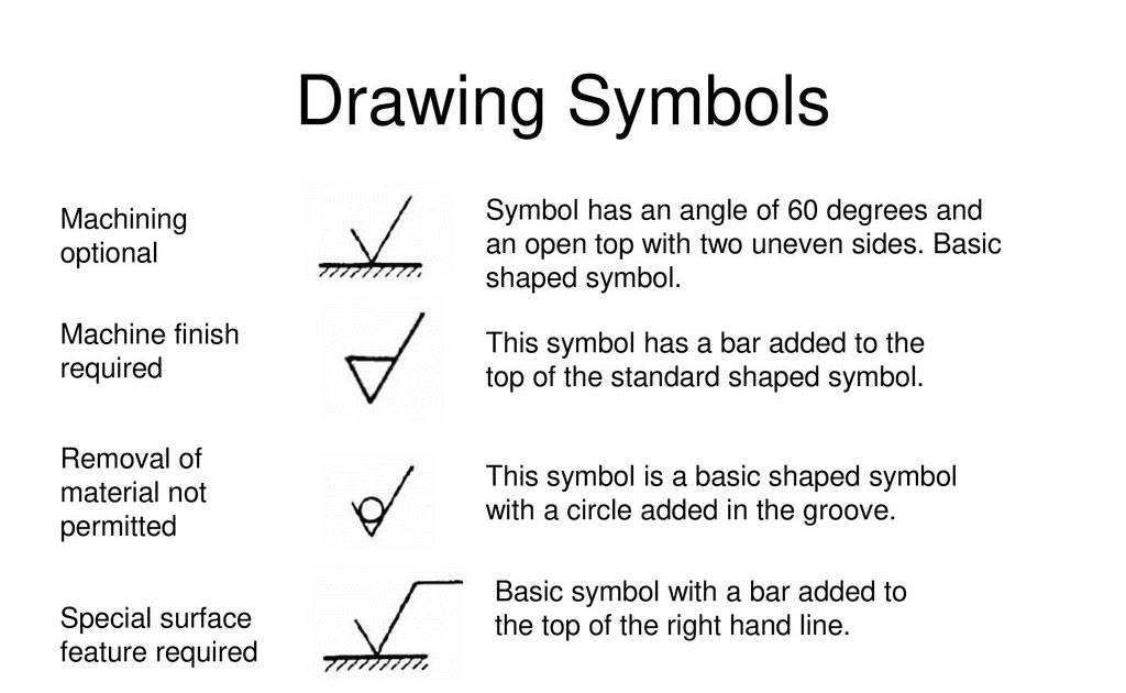
Technical Drawing Symbols

Mechanical Drawing Symbols from Mechanical Engineering — Welding

GD&T Symbols Reference Guide from Sigmetrix Mechanical design

Engineering Drawing Symbols And Their Meanings Pdf at PaintingValley

Mechanical Engineering Symbols And Their Meanings
Machine Drawing Symbols

Mechanical Drawing Symbols

Mechanical Engineering Drawing Symbols Pdf Free Download at

Mechanical Drawing Symbols ERD Symbols and Meanings Quality Control
Web How To Read Machine Drawings?
Pictures Of Each Symbol Included.
Web Geometric Dimensioning And Tolerancing (Gd&T) Consists Of A Set Of Symbols And Rules For Applying Them That Communicates The Requirements Of An Engineering Blueprint.
Name And Address Of The Company Or Agency Who Prepared Or Owns The Drawing.
Related Post: