Mechanical Line Drawing
Mechanical Line Drawing - The width of the line should be chosen from one of the following. The series is based on the common ratio of 1:√2 or 1:1.4. Web one of the best ways to communicate one’s ideas is through some form of picture or drawing. Web mechanical systems drawing is a type of technical drawing that shows information about heating, ventilating, and air conditioning. An engineering (or technical) drawingis a graphical representation of a part, assembly, system, or structure and it can be produced using freehand, mechanical tools, or computer methods. In this article, we will learn the various types of lines that are widely. In general application, thick lines are 0.6 mm (.024”). Web what are centerlines? The purpose is to convey all the information necessary for manufacturing a product or a part. It is more than simply a drawing, it is a graphical language that communicates ideas and information. Web what are centerlines? These drawings are often a set of detailed drawings used for construction projects; See mechanic line drawing stock video clips image type orientation color people artists sort by popular transportation and travel car types technology jobs/professions abstract designs and shapes motor car Understand the scope of the project. It is a powerful tool that helps analyze. The series is based on the common ratio of 1:√2 or 1:1.4. In general application, thick lines are 0.6 mm (.024”). The skills learned through technical drawing lessons extend from paper to blueprints to computer assisted drawings. Centerlines are one of the most frequently used tools in engineering drawing. 0.13 mm, 0.18mm, 0.25 mm, 0.35 mm, 0.50mm, 0.70mm, 1.0mm, 1.4. Web smartdraw provides thousands of mechanical drawing symbols that you can drag and drop, then add lines and text. In this article, we will learn the various types of lines that are widely. Generally, lines of three different widths. Your first step when you receive a set of drawings is to review all of the essential information about the project:. Web mechanical systems drawing is a type of technical drawing that shows information about heating, ventilating, air conditioning and transportation around the building (elevators or lifts and escalator). Web linetypes and weight standards in technical drawing. Web smartdraw provides thousands of mechanical drawing symbols that you can drag and drop, then add lines and text. Vertical lines, horizontal lines, diagonal. “sketching” generally means freehand drawing. Web 18.06.2020 by andreas velling engineering drawing basics explained an engineering drawing is a subcategory of technical drawings. Web there are 5 main types of lines in art: Web this youtube channel is dedicated to teaching people how to improve their technical drawing skills. An engineering (or technical) drawingis a graphical representation of a part,. Web watch on blue print, mechanical line this line quality is the simplest, most straightforward line quality there is in drawing. It focusses on drawing figures from the geometric plane to descriptive geometry and also. Understand the scope of the project. The width of the line should be chosen from one of the following. Generally, lines of three different widths. The width of the line should be chosen from one of the following. In general application, thick lines are 0.6 mm (.024”). Vertical lines, horizontal lines, diagonal lines, zigzag lines, and curved lines. Common examples of such features include bolt holes, pins, discs, etc. Generally, lines of three different widths. “sketching” generally means freehand drawing. It focusses on drawing figures from the geometric plane to descriptive geometry and also. The purpose is to convey all the information necessary for manufacturing a product or a part. See mechanic line drawing stock video clips image type orientation color people artists sort by popular transportation and travel car types technology jobs/professions abstract designs. The purpose is to convey all the information necessary for manufacturing a product or a part. The basic materials include paper, pencils, drafting triangles and specialized scales. Web types of lines used in engineering drawing contents show following are the different types of lines used in engineering drawing: Web mechanical systems drawing is a type of technical drawing that shows. Web watch on blue print, mechanical line this line quality is the simplest, most straightforward line quality there is in drawing. In this article, we will learn the various types of lines that are widely. An engineering (or technical) drawingis a graphical representation of a part, assembly, system, or structure and it can be produced using freehand, mechanical tools, or. Web 18.06.2020 by andreas velling engineering drawing basics explained an engineering drawing is a subcategory of technical drawings. Web the selection of the width of the line depends on the scale, size, and type of the drawing. Web what are centerlines? These drawings are often a set of detailed drawings used for construction projects; An engineering (or technical) drawingis a graphical representation of a part, assembly, system, or structure and it can be produced using freehand, mechanical tools, or computer methods. Web mechanical systems drawing is a type of technical drawing that shows information about heating, ventilating, and air conditioning. Web types of lines used in engineering drawing contents show following are the different types of lines used in engineering drawing: Web mechanical systems drawing is a type of technical drawing that shows information about heating, ventilating, air conditioning and transportation around the building (elevators or lifts and escalator). Web straight and curved lines are parallel when the shortest distance between them remains constant. In this article, we will learn the various types of lines that are widely. Engineering drawings use standardised language and symbols. Web watch on blue print, mechanical line this line quality is the simplest, most straightforward line quality there is in drawing. It is a requirement for all hvac work. Web how do you read mechanical drawings? Again, lines are differentiated as thick lines (0.6 mm thickness), thin lines (0.3 mm thick), continuous lines, dashed lines, freehand lines, zigzag lines, chain lines, etc. Web mechanical drawings serve as communication for engineers, architects, machinists and contractors.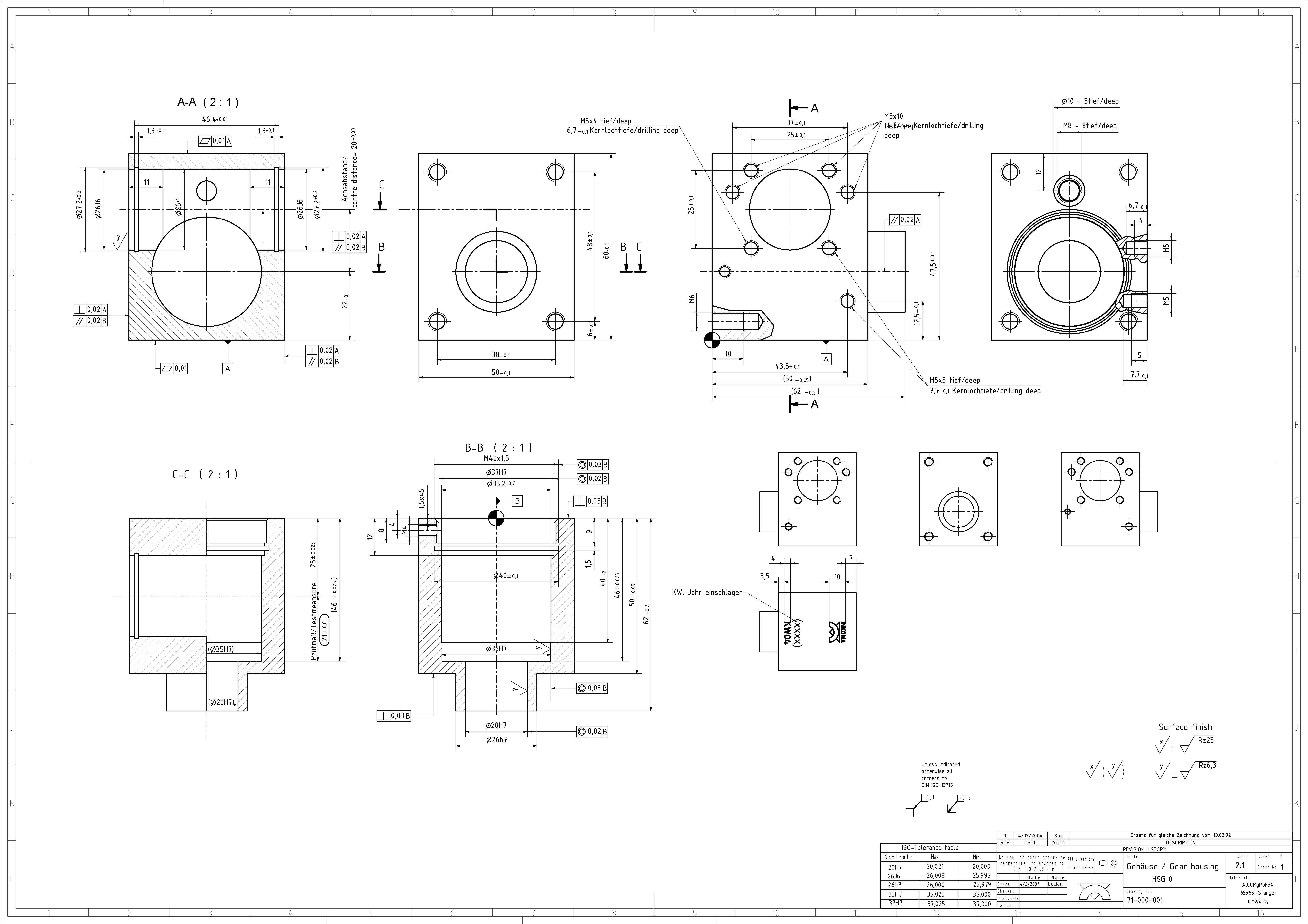
Autocad Mechanical Drawing Samples at GetDrawings Free download

Understanding Mechanical Drawings Mechanical Drafting Course

Mechanical Drawings bartleby
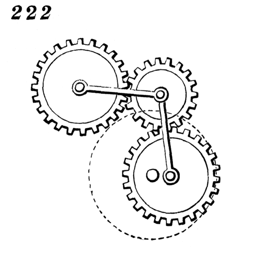
2D Drawing Mechanical Movement 222 ENGI 210 Prototyping and

Pin on Mechanical drawings / Blueprints / CAD Drawings
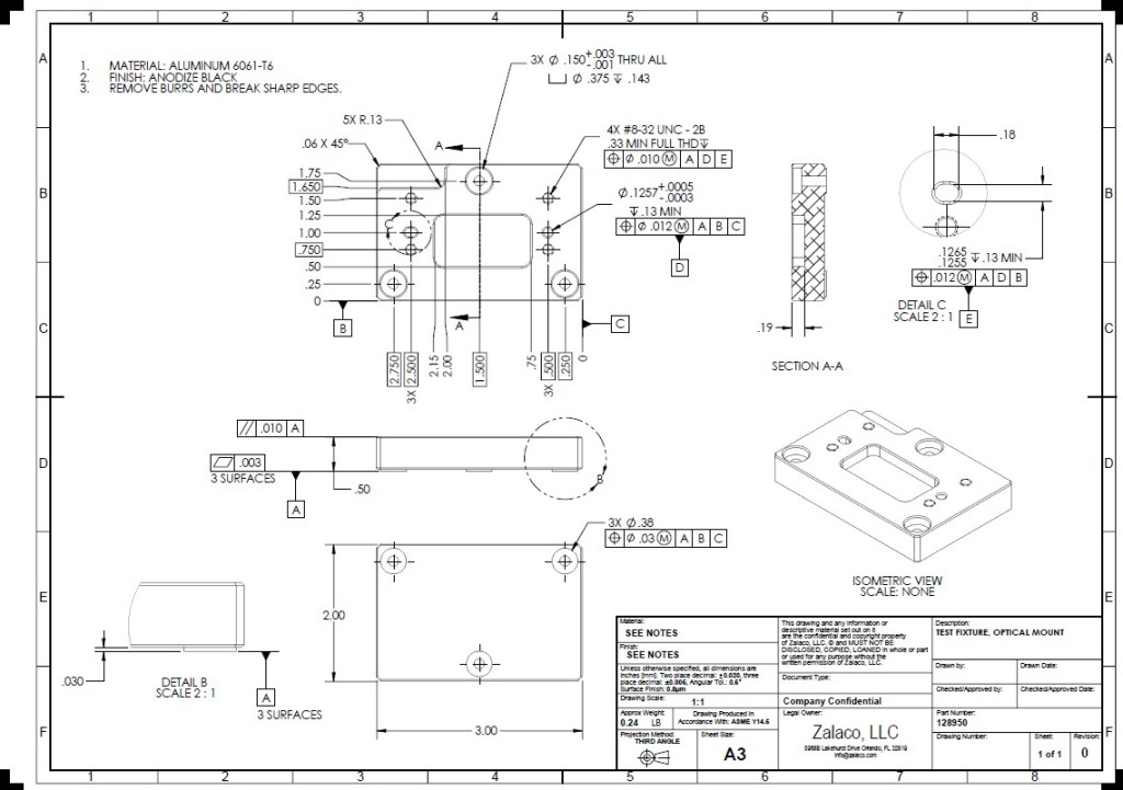
Mechanical Drafting and Documentation Zalaco, LLC

Mechanical Engineer Drawing at GetDrawings Free download
Autocad Mechanical Drawing Samples at GetDrawings Free download

Mechanical Drawings bartleby
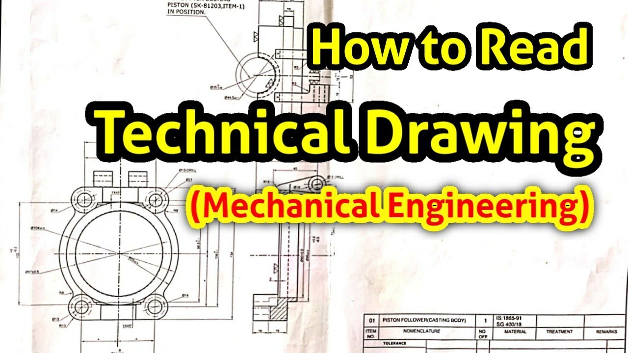
how to read technical drawing (Mechanical Engineering) YouTube
Web There Are 5 Main Types Of Lines In Art:
[1] It Is A Powerful Tool That Helps Analyze Complex Systems.
Their Basic Purpose Is To Show Circular/Cylindrical Features In A Drawing, Which Are Found In Abundance In Mechanical Parts.
Details About The Types And Grades Of Materials To Be Used.
Related Post: