One Line Drawings Electrical
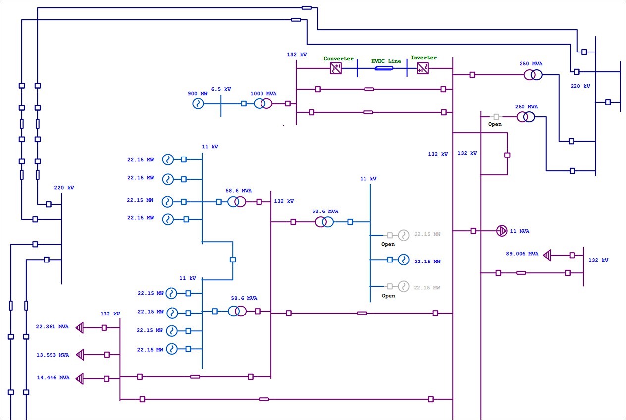
One Line Drawings Electrical - Diagrams start at the top of the page with the incoming source of a system’s power. Ladder diagram or line diagram. The purpose of single line diagram is to diagrammatically show sources of power, electrical equipment loads, electrical drives, system details and fault levels. Basics 10 480 v pump schematic : Symbols and lines are used to represent the nodes and connections in the system, and electrical characteristics may be included as well. It is the first step in preparing a critical response plan, allowing you to become thoroughly familiar with the electrical distribution system layout and design in your facility. One of the key tools in developing and documenting an electrical power system is the single line diagram (shortened sld). Web by r jagan mohan rao. Web we usually depict the electrical distribution system by a graphic representation called a single. Basically, they are simplified and digest picture of whole switchboard, showing only major power equipment and connections to other switchboards, usually with addition of major. Web single line diagrams are used in common engineering practice as graphical representation of electrical switchboard or assembly containing more sections, i.e. Basics 9 4.16 kv pump schematic : Web we usually depict the electrical distribution system by a graphic representation called a single. Electrical power grids primarily consist of. Basically, they are simplified and digest picture of whole switchboard,. Web we usually depict the electrical distribution system by a graphic representation called a single. Web electrical one line diagram design. Symbols and lines are used to represent the nodes and connections in the system, and electrical characteristics may be included as well. It is a simplified drawing of the whole system or a portion of the power system that. The purpose of single line diagram is to diagrammatically show sources of power, electrical equipment loads, electrical drives, system details and fault levels. Web what is the single line diagram? Sdm metro can help you keep track of and understand your power. It will have one single line shown for bus (or cable) to represent all three phases. Web we. It is a simplified drawing of the whole system or a portion of the power system that shows the electrical placement of all major equipment. Basically, they are simplified and digest picture of whole switchboard, showing only major power equipment and connections to other switchboards, usually with addition of major. A single line can show all or part of a. Web an electrical one line diagram (or single line diagram, sld) is a simplified drawing used to represent the power system in a plant. Also, look at electrical power distribution diagrams, including protective relays, and other one lines. Ladder diagram or line diagram. Diagrams start at the top of the page with the incoming source of a system’s power. Web. Symbols and lines are used to represent the nodes and connections in the system, and electrical characteristics may be included as well. Basics 9 4.16 kv pump schematic : Web we usually depict the electrical distribution system by a graphic representation called a single. It will have one single line shown for bus (or cable) to represent all three phases.. Web we usually depict the electrical distribution system by a graphic representation called a single. Basics 9 4.16 kv pump schematic : Electrical power grids primarily consist of. A single line can show all or part of a system. It will have one single line shown for bus (or cable) to represent all three phases. Diagrams start at the top of the page with the incoming source of a system’s power. Web single line diagrams are used in common engineering practice as graphical representation of electrical switchboard or assembly containing more sections, i.e. Web an electrical one line diagram (or single line diagram, sld) is a simplified drawing used to represent the power system in. Basics 9 4.16 kv pump schematic : Main components such as transformers, switches, and breakers are indicated by their standard graphic symbol. Also, look at electrical power distribution diagrams, including protective relays, and other one lines. Sdm metro can help you keep track of and understand your power. Electrical elements such as circuit breakers, transformers, capacitors, bus bars, and conductors. One of the key tools in developing and documenting an electrical power system is the single line diagram (shortened sld). Web single line diagrams are used in common engineering practice as graphical representation of electrical switchboard or assembly containing more sections, i.e. Electrical power grids primarily consist of. It is the first step in preparing a critical response plan, allowing. One of the key tools in developing and documenting an electrical power system is the single line diagram (shortened sld). Electrical power grids primarily consist of. First of all, power system designers should always communicate their design requirements through a combination of drawings, schedules and technical specifications. When expanding or renovating, it is important to know how power is distributed throughout your facility before work begins, and keep track of changes after work is completed. This condenses the space and complexity of the diagram for simpler troubleshooting. Electrical elements such as circuit breakers, transformers, capacitors, bus bars, and conductors are shown by standardized. Basics 9 4.16 kv pump schematic : It will have one single line shown for bus (or cable) to represent all three phases. Web what is the single line diagram? The purpose of single line diagram is to diagrammatically show sources of power, electrical equipment loads, electrical drives, system details and fault levels. Diagrams start at the top of the page with the incoming source of a system’s power. Basics 10 480 v pump schematic : Main components such as transformers, switches, and breakers are indicated by their standard graphic symbol. It is a simplified drawing of the whole system or a portion of the power system that shows the electrical placement of all major equipment. Sdm metro can help you keep track of and understand your power. Basically, they are simplified and digest picture of whole switchboard, showing only major power equipment and connections to other switchboards, usually with addition of major.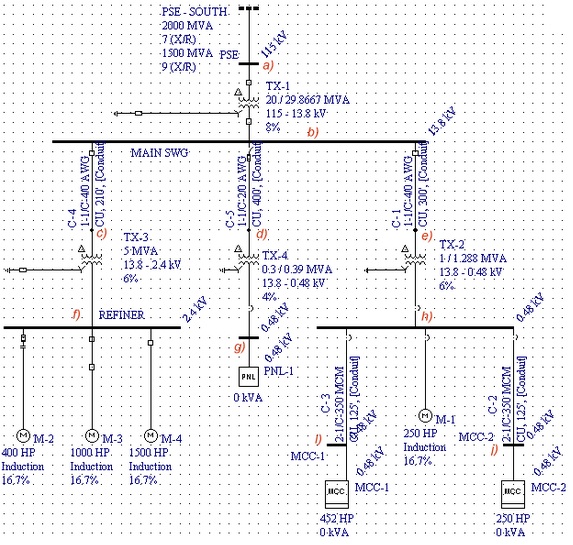
Electrical Single Line Diagram Part Two Electrical Knowhow
Intelligent One Line Diagram Electrical SingleLine Diagram ETAP
Electrical SingleLine Diagram Electrical OneLine Diagram ETAP
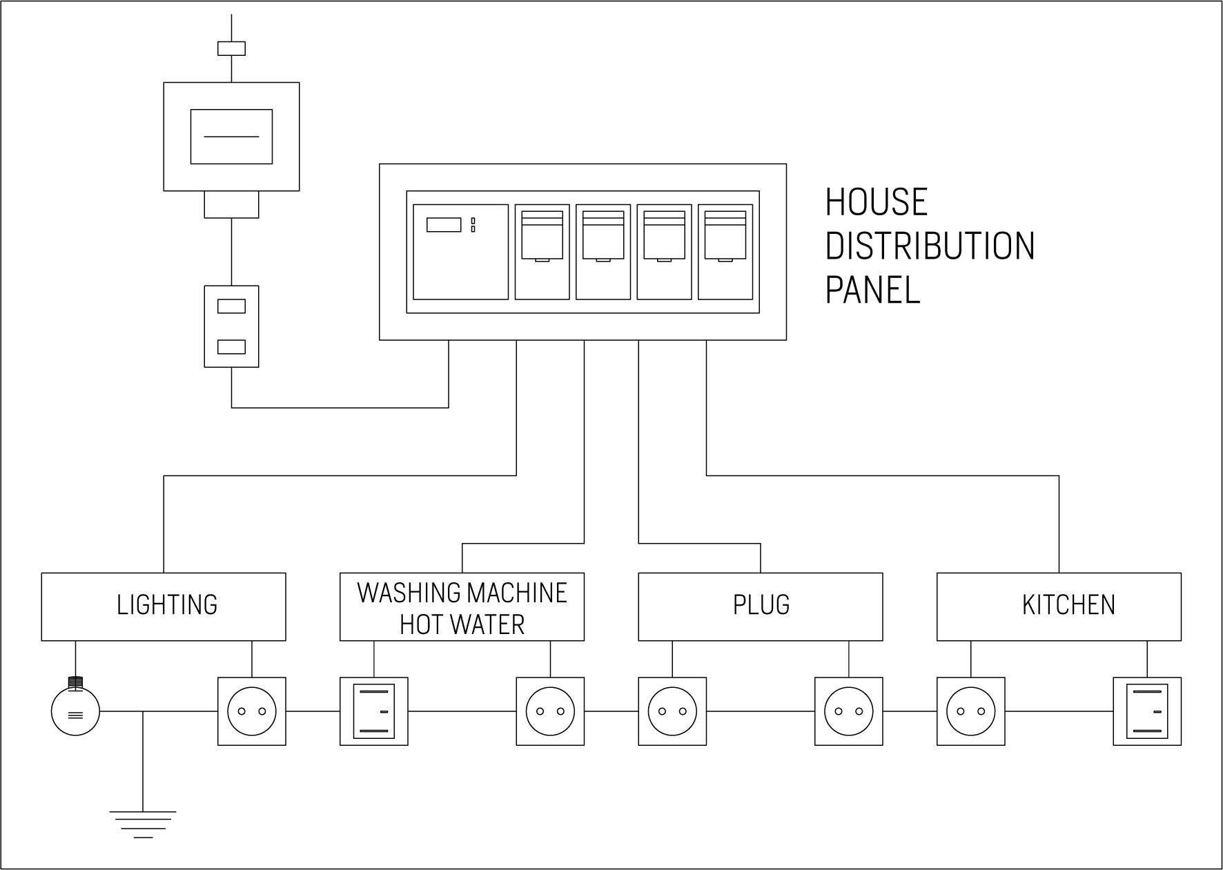
Single Line Diagram Of Electrical House Wiring Wiring Diagram and
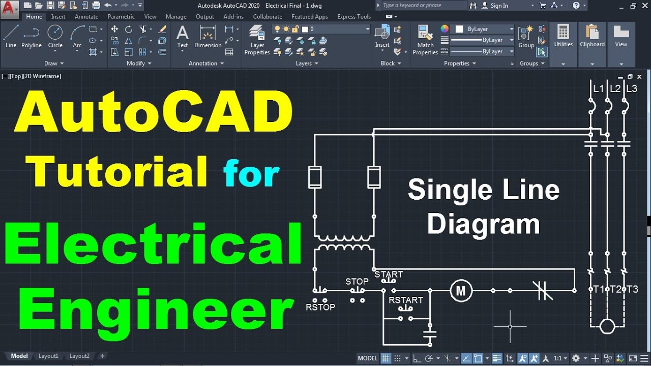
AutoCAD Single Line Diagram Drawing Tutorial for Electrical Engineers
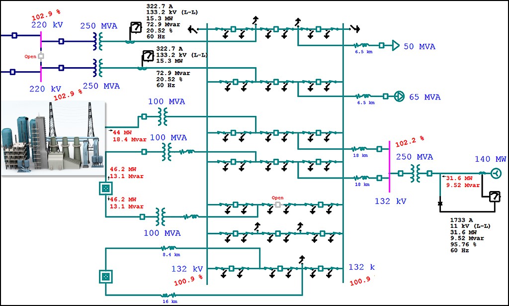
Electrical SingleLine Diagram Electrical OneLine Diagram ETAP

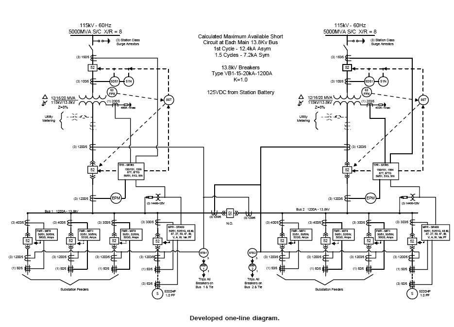
Electrical Diagrams and Schematics Inst Tools
Electrical Single Line Diagram Part Two Electrical Knowhow
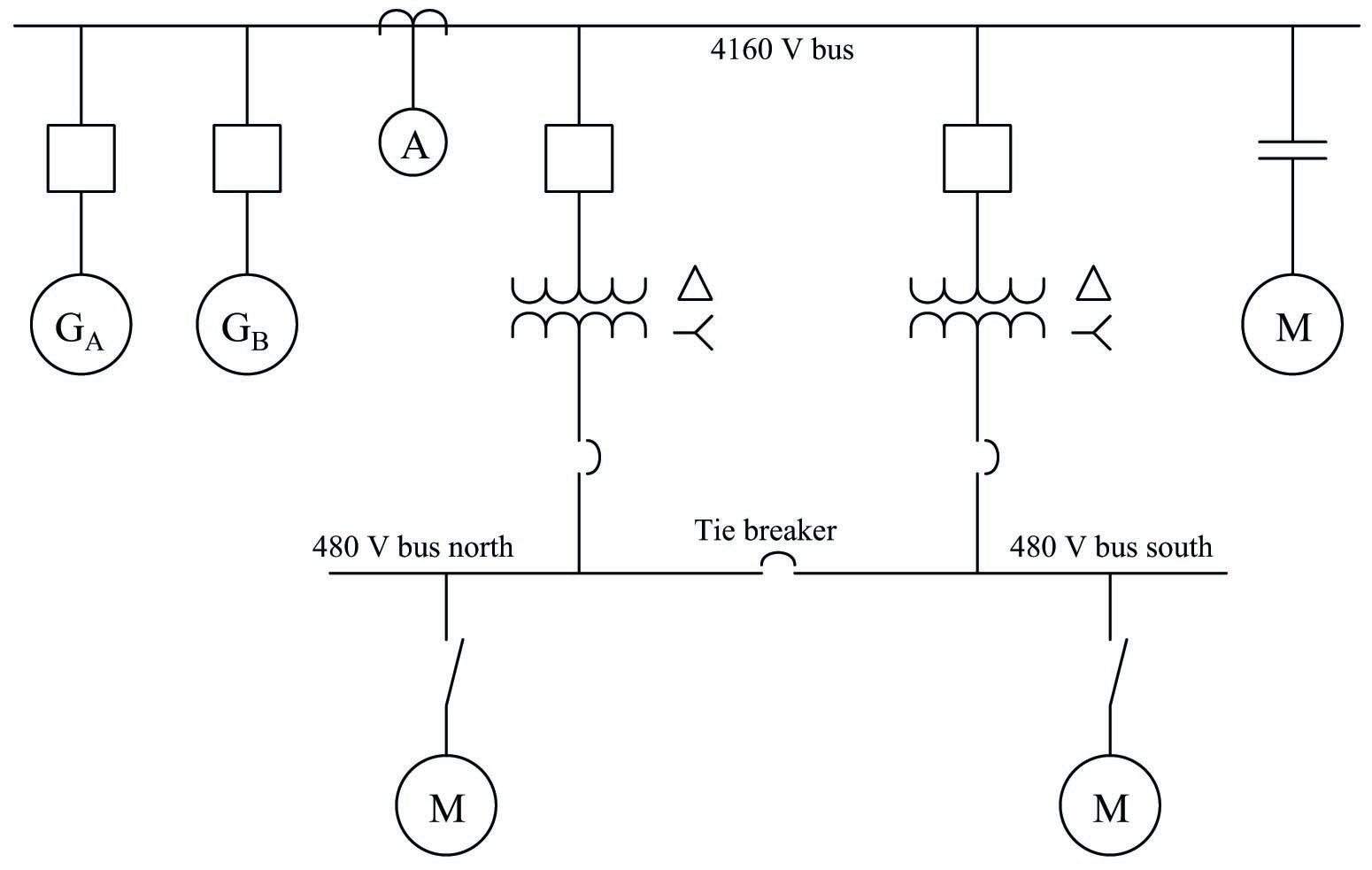
single line diagram of electrical house wiring Wiring Diagram and

Single Line Diagram Electrical Drawing Software Free LT Panel Design
It Is The First Step In Preparing A Critical Response Plan, Allowing You To Become Thoroughly Familiar With The Electrical Distribution System Layout And Design In Your Facility.
Basics 8 Aov Elementary & Block Diagram :
Web Single Line Diagrams Are Used In Common Engineering Practice As Graphical Representation Of Electrical Switchboard Or Assembly Containing More Sections, I.e.
Web We Usually Depict The Electrical Distribution System By A Graphic Representation Called A Single Line Diagram (Sld).
Related Post: