Pipe Drawing Symbols
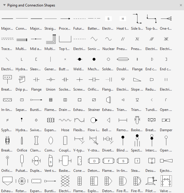
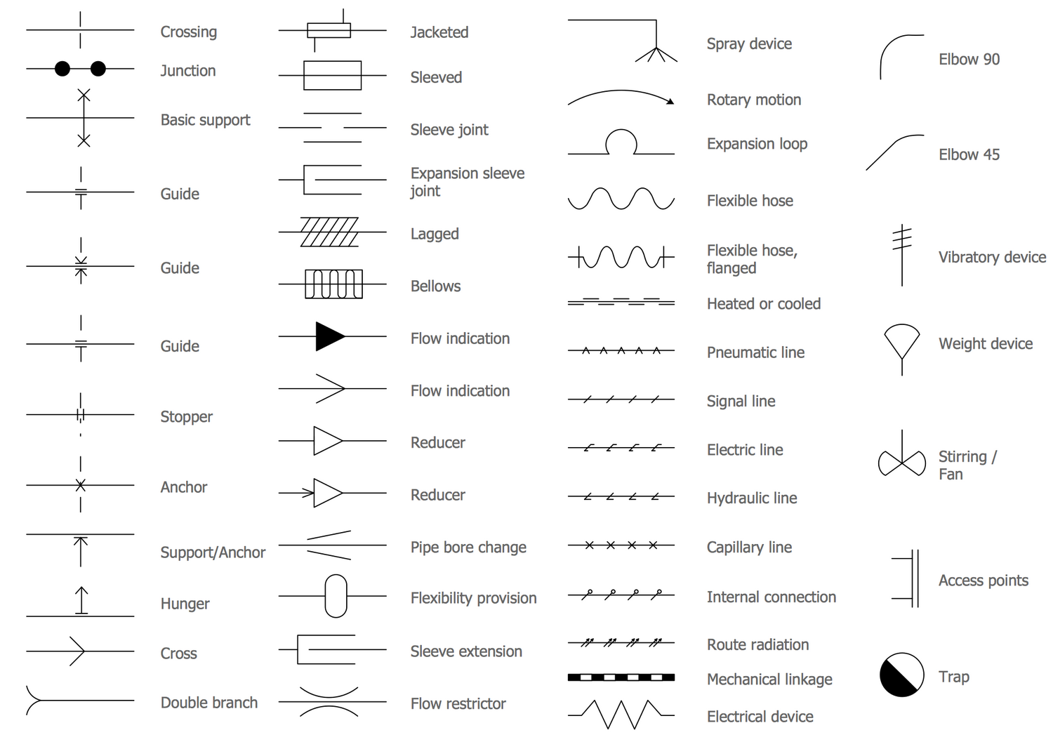
Pipe Drawing Symbols - Web piping isometric drawing consists of three sections. There may be multiple symbols for one fitting or part depending on the fashion it is to be installed (butt weld, socket weld, threaded.) Note that, although the auxiliary piping symbols identify their mediums, the symbol for the process flow line does not identify its medium. Web a complete collection of the most used p&id symbols for lines, piping, valves, instruments, pumps, compressors, pressure equipment and other mechanical equipment, and the pdf file for p&id symbols to download. For example if a 90 degree elbow is to be placed in service the drawing will reflect a 90 degree angle. Web as with weld symbols, pipe symbols are a reflection of what that part would look like in theory. Web isometric drawings excel at visually portraying pipeline systems, capturing the intricate network of pipes, valves, fittings, and connections in a manner that is both understandable and standardized. Any instrument attached to a piping system can be easily known with. These various types of piping drawings in engineering organizations are: These symbols can represent actuators, sensors, and controllers and may be apparent in most, if not all, system diagrams. Main graphic section consist of isometric representation of a pipe line route in 3d space, which includes following information : There may be multiple symbols for one fitting or part depending on the fashion it is to be installed (butt weld, socket weld, threaded.) Web isometric drawings excel at visually portraying pipeline systems, capturing the intricate network of pipes, valves,. 5 provides symbols for fans, pumps, and turbines. Web a complete collection of the most used p&id symbols for lines, piping, valves, instruments, pumps, power, pressure equipment and other mechanical hardware, and the pdf create for p&id symbols to download. These symbols are used to indicate the type of connection, the direction of flow, and the size of the pipe.. Lighter lines show connected pipe, and are not parts of the symbols. Various symbols are used to indicate piping components, instrumentation, equipments in engineering drawings such as piping and instrumentation diagram (p&id), isometric drawings, plot plan, equipment layout, welding drawings etc. Web a complete collection of the most used p&id symbols for lines, piping, valves, instruments, pumps, power, pressure equipment. Piping and pipeline drawing symbols throw lights on the type of joint like buttweld, socket weld, or threaded. Web figure 7 shows commonly used symbols for indicating the medium carried by the piping and for differentiating between piping, instrumentation signals, and electrical wires. 2.7 figure 7 provides symbols for pipe and pipe fittings. There may be multiple symbols for one. Web piping symbols, also known as pipe drawings, are a set of symbols used in metal fabrication drawings to represent the various types of pipes and fittings used in industrial piping systems. These symbols are used to indicate the type of connection, the direction of flow, and the size of the pipe. Piping and pipeline drawing symbols throw lights on. Accurate drawing symbols, callouts, precise coordinates, and elevations provide intricate information to the fabricator. Web as with weld symbols, pipe symbols are a reflection of what that part would look like in theory. For example if a 90 degree elbow is to be placed in service the drawing will reflect a 90 degree angle. These symbols are used to indicate. Web as with weld symbols, pipe symbols are a reflection of what that part would look like in theory. Web knowing the piping drawing symbols will provide various information like: Web piping symbols, also known as pipe drawings, are a set of symbols used in metal fabrication drawings to represent the various types of pipes and fittings used in industrial. Lighter lines show connected pipe, and are not parts of the symbols. Web isometric drawings excel at visually portraying pipeline systems, capturing the intricate network of pipes, valves, fittings, and connections in a manner that is both understandable and standardized. Web a complete collection of the most used p&id symbols for lines, piping, valves, instruments, pumps, power, pressure equipment and. Web isometric drawing symbols for piping fittings blind flange buttweld 45 degree elbow buttweld 90 degree elbow buttweld cap buttweld concentric reducer buttweld eccentric reducer buttweld elbow buttweld equal tee buttweld reducing tee flangolet lap joint flange nipolet slip on flange socketweld 45 degree elbow socketweld 90 degree elbow 2.6 figure 6 provides symbols for plumbing components. Web plot plan. There may be multiple symbols for one fitting or part depending on the fashion it is to be installed (butt weld, socket weld, threaded.) Web the process of drafting isometric drawings for a pipeline system involves referencing the arrangements of the pipelines, sections, and elevation drawings during its development. For example if a 90 degree elbow is to be placed. Web piping and instrumentation diagrams (p&ids) use specific symbols to show the connectivity of equipment, sensors, and valves in a control system. Web piping and instrument diagram standard symbols detailed documentation provides a standard set of shapes & symbols for documenting p&id and pfd, including standard shapes of instrument, valves, pump, heating exchanges, mixers, crushers, vessels, compressors, filters, motors and connecting shapes. Web these symbols are categorized under the following headings: Web isometric drawings excel at visually portraying pipeline systems, capturing the intricate network of pipes, valves, fittings, and connections in a manner that is both understandable and standardized. 2.8 figure 8 provides symbols for noise control components and designations. Lighter lines show connected pipe, and are not parts of the symbols. Piping and pipeline drawing symbols throw lights on the type of joint like buttweld, socket weld, or threaded. 2.7 figure 7 provides symbols for pipe and pipe fittings. For example if a 90 degree elbow is to be placed in service the drawing will reflect a 90 degree angle. Web build your custom piping and instrumentation diagrams with professional symbols for motors, flow meters, segmented pipes, pumps, tanks, valves, sensors, process cooling, process heating, water and wastewater systems, and much more. 5 provides symbols for fans, pumps, and turbines. Web plumbing symbols enable an architect to effectively install, locate, and fix the pipelines and plumbing tools into the building. Web a complete collection of the most used p&id symbols for lines, piping, valves, instruments, pumps, compressors, pressure equipment and other mechanical equipment, and the pdf file for p&id symbols to download. 2.6 figure 6 provides symbols for plumbing components. Web knowing the piping drawing symbols will provide various information like: Note that, although the auxiliary piping symbols identify their mediums, the symbol for the process flow line does not identify its medium.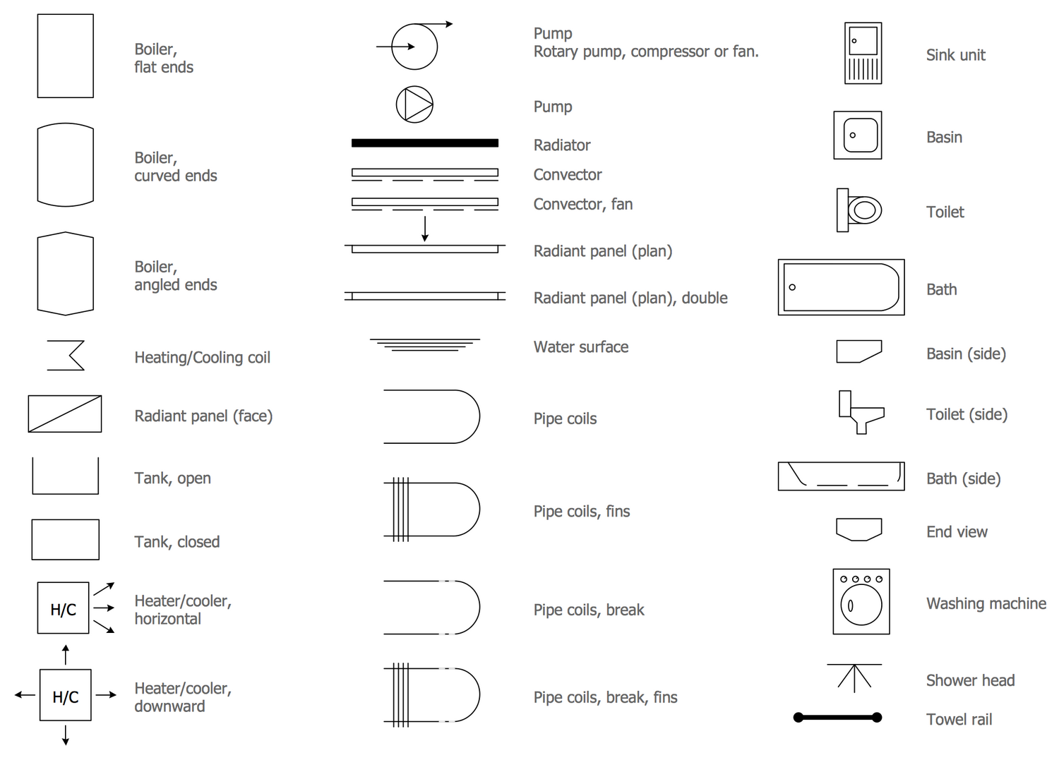
Piping Isometric Drawing Symbols Pdf at Explore

What is Piping Isometric drawing? How to Read Piping Drawing? ALL

Piping Isometric Drawing Symbols Pdf at Explore
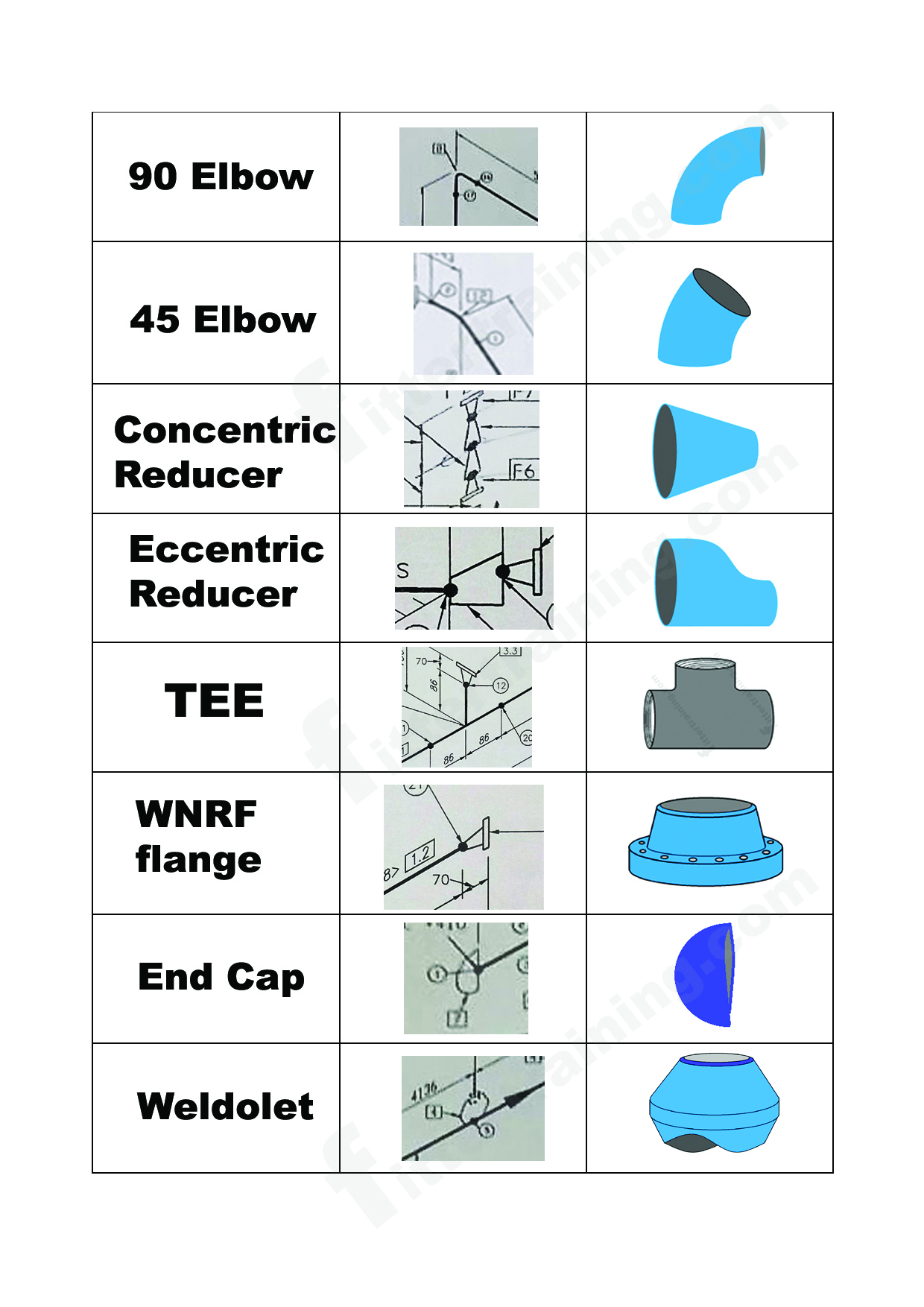
isometric pipe drawing fittings symbol Fitter training

Basic Piping Isometric Symbols Piping Analysis YouTube
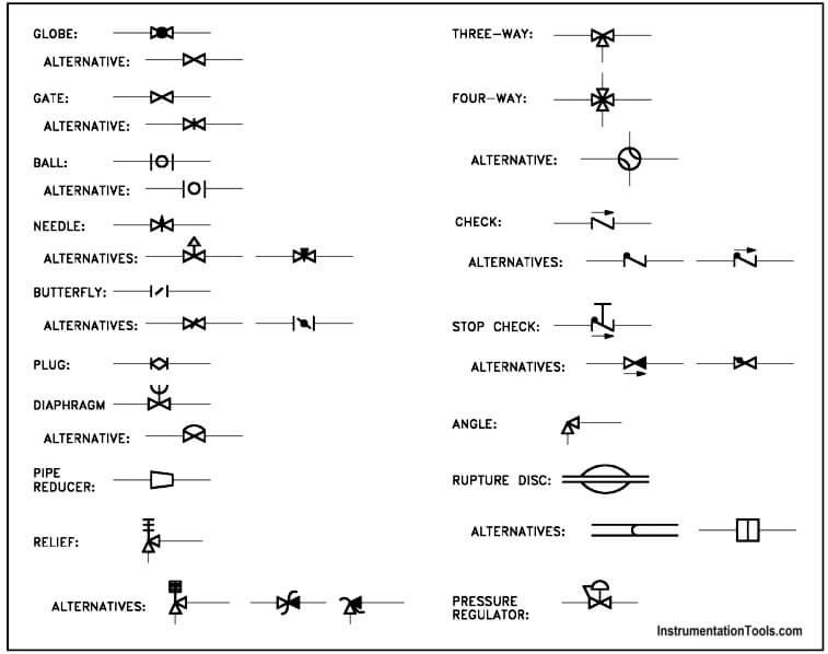
Piping and Instrumentation Symbols Instrumentation Tools
Plumbing and Piping Plan Symbols Edraw
Piping and Instrumentation Diagram Software

Piping Isometric Drawings The Piping Engineering World
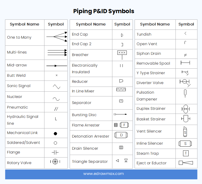
P&ID Symbols and Meanings EdrawMax Online
Here Introduces The Plumbing And Piping Symbols, And How To Find Or Use Them In Edrawmax, Just Try It Free Now!
Accurate Drawing Symbols, Callouts, Precise Coordinates, And Elevations Provide Intricate Information To The Fabricator.
For Example If A 90 Degree Elbow Is To Be Placed In Service The Drawing Will Reflect A 90 Degree Angle.
7 Provides Symbols For Pipe And Pipe Fittings.
Related Post: