Pipe Engineering Drawing
Pipe Engineering Drawing - Web this chapter is an overview of the pipe drafting and design profession. They serve as precise illustrations providing essential information about the layout, dimensions, materials, and key components of a pipeline system. The plan and section method is the conventional or classical drawing procedure of orthogonal projections. Web piping engineering is a specialized discipline of mechanical engineering that deals with the design of piping and layout of equipment and process units in chemical, petrochemical or hydrocarbon facilities. Various symbols are used to indicate piping components, instrumentation, equipments in engineering drawings such as piping and instrumentation diagram (p&id), isometric drawings, plot plan, equipment layout, welding drawings etc. Web piping isometric drawing is an isometric representation of single pipe line in a plant. Typically a piping & instrumentation diagram (p&id) drawing sets the fundamental requirements showing the pipe size, schematic of the equipment. Web how to read isometric drawing in a piping isometrics drawing, pipe is drawn according to it’s length, width and depth, and often shown in a single view. Explain the various pipe manufacturing and joining methods. Checkout list of such symbols given below. Web test your knowledge with our 300+ quiz questions. Visible lines hidden lines section lines center lines dimension lines extension lines leader lines cutting plane lines break lines phantom lines borderlines arrowheads visible lines they are dark and thick lines of any engineering design drawing. Web this chapter is an overview of the pipe drafting and design profession. Identify the. Web piping engineering is a specialized discipline of mechanical engineering that deals with the design of piping and layout of equipment and process units in chemical, petrochemical or hydrocarbon facilities. Many abbreviations are common and are regularly used in the drawings but few of the abbreviation are new and unique for a particular drawing. The plan and section method is. Web isometric drawings, often referred to as isometrics, are a type of 3d representation that offers a unique angled view of objects. Web piping design is a critical discipline in mechanical engineering that involves the planning, layout, and specification of the systems used to transport fluids, gases, and other materials in the. Explain the various pipe manufacturing and joining methods.. Build a strong understanding of piping design and construction principles for both metallic and nonmetallic piping systems. It is the most important deliverable of piping engineering department. Web piping isometric drawing is an isometric representation of single pipe line in a plant. Various symbols are used to indicate piping components, instrumentation, equipments in engineering drawings such as piping and instrumentation. Checkout list of such symbols given below. Web 42k views 1 year ago tutorials for pipe fitters and fabricators. Web piping engineering drawings and documents. Whenever you start reading a piping drawing or document, you can see many abbreviations on these drawings/documents. It lists the various facility types where pipe drafting and design is applied and the types of companies. Build a strong understanding of piping design and construction principles for both metallic and nonmetallic piping systems. In the context of pipeline design and engineering, isometric drawings have assumed a significant role. Plan view at different elevations are prepared. Web this chapter is an overview of the pipe drafting and design profession. Piping isometric drawing consists of three sections. Web engineering drawings are the industry’s means of communicating detailed and accurate information on how to fabricate, assemble, troubleshoot, repair, and operate a piece of equipment or a system. The isometrics drawing are created from. The types of drawings developed by pipe drafters and the engineering groups that use them are reviewed. These drawings are developed from the schematics, basic. Build a strong understanding of piping design and construction principles for both metallic and nonmetallic piping systems. Visible lines hidden lines section lines center lines dimension lines extension lines leader lines cutting plane lines break lines phantom lines borderlines arrowheads visible lines they are dark and thick lines of any engineering design drawing. Web piping engineering drawings and documents. Identify. Web piping isometric drawing software is an essential tool for piping engineers and designers to create detailed isometric drawings of piping systems. Web engineering drawings are the industry’s means of communicating detailed and accurate information on how to fabricate, assemble, troubleshoot, repair, and operate a piece of equipment or a system. Identify the different types of fittings and their application.. Web how to read isometric drawing in a piping isometrics drawing, pipe is drawn according to it’s length, width and depth, and often shown in a single view. The plan and section method is the conventional or classical drawing procedure of orthogonal projections. Web piping & instrument diagrams piping & instrument diagrams barry m barkel pe communication for engineers verbal. Web isometric drawings, often referred to as isometrics, are a type of 3d representation that offers a unique angled view of objects. Build a strong understanding of piping design and construction principles for both metallic and nonmetallic piping systems. In the context of pipeline design and engineering, isometric drawings have assumed a significant role. Various symbols are used to indicate piping components, instrumentation, equipments in engineering drawings such as piping and instrumentation diagram (p&id), isometric drawings, plot plan, equipment layout, welding drawings etc. Web there are 12 types of lines usually used in engineering drawing. Piping general arrangement drawings describe the arrangement of piping and may be drawn as plans and elevations. Identify the different types of fittings and their application. Web piping engineering is a specialized discipline of mechanical engineering that deals with the design of piping and layout of equipment and process units in chemical, petrochemical or hydrocarbon facilities. It is the most important deliverable of piping engineering department. There are different types of piping diagrams and they are process flow diagrams, piping and instrumentation diagram, orthographic pipe drawing, piping isometrics, and block flow diagrams. Piping isometric drawing consists of three sections. Web piping engineering drawings and documents. Typically a piping & instrumentation diagram (p&id) drawing sets the fundamental requirements showing the pipe size, schematic of the equipment. Web how to read isometric drawing in a piping isometrics drawing, pipe is drawn according to it’s length, width and depth, and often shown in a single view. These various types of piping drawings in engineering organizations are: Whenever you start reading a piping drawing or document, you can see many abbreviations on these drawings/documents.
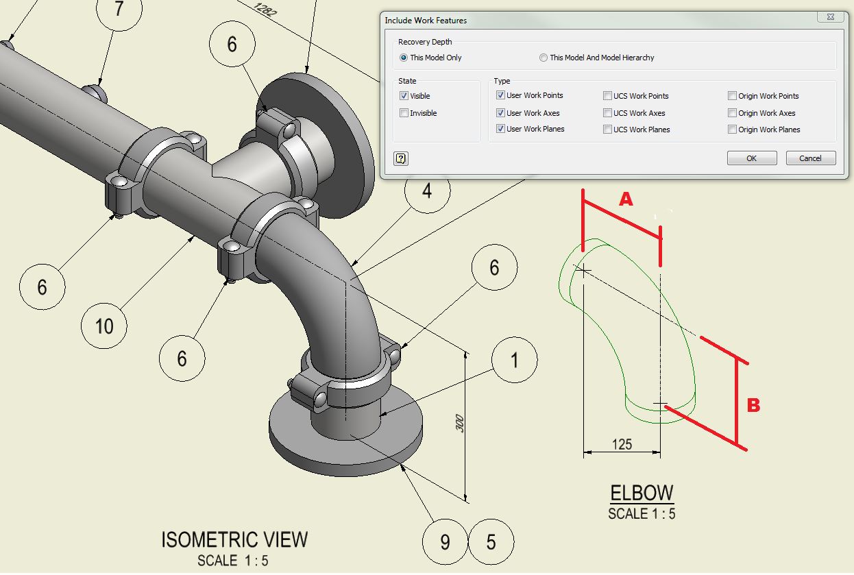
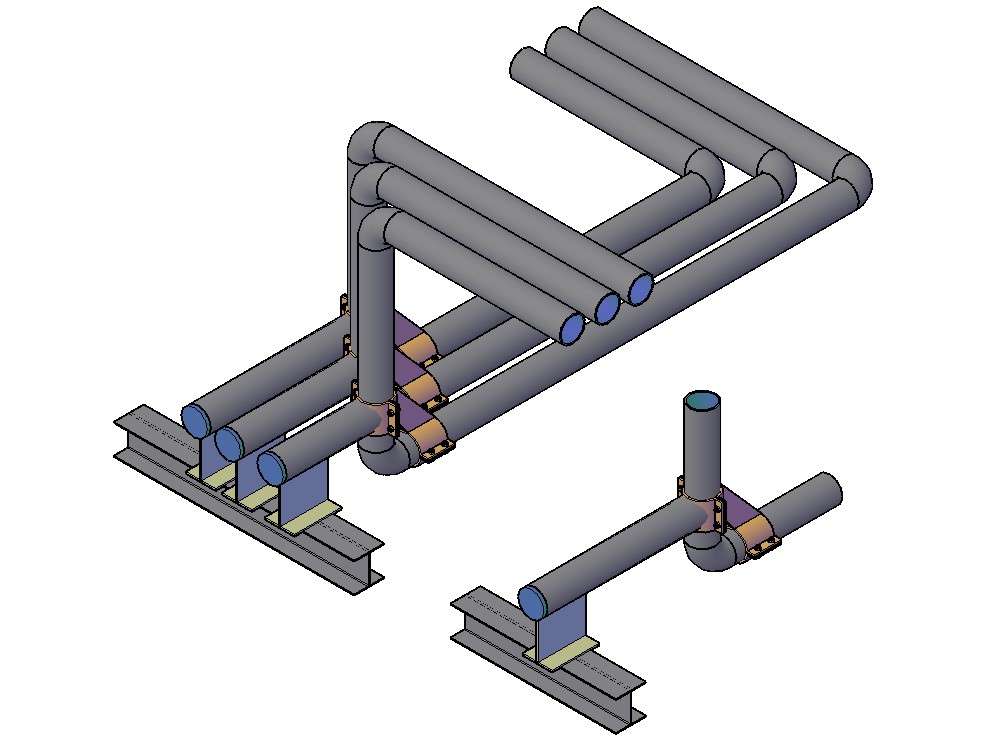
Creating a pipe that bends in multiple directions at once in Autodesk
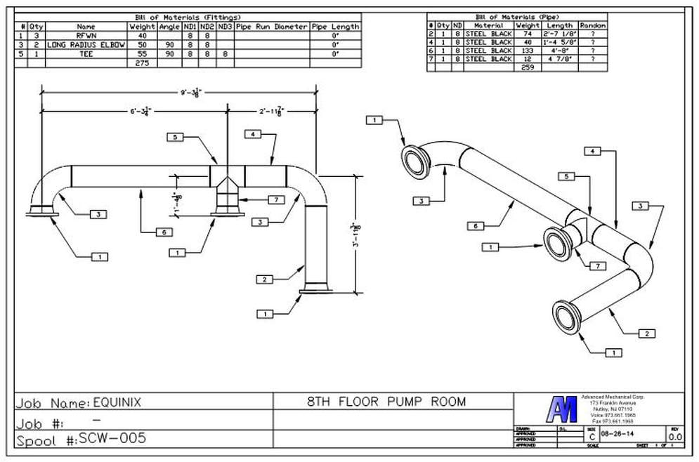
Isometric Piping Drawings Advenser

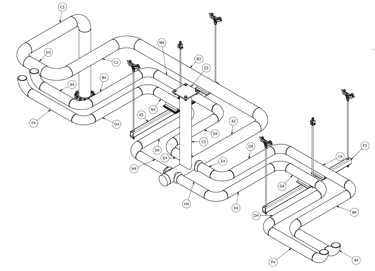
pipedrawing STRUCTURAL

How to read isometric drawing piping dadver
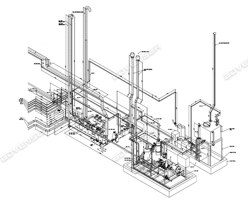
PIPING DRAWINGS
Isometric Piping Drawing Sketch Coloring Page
Piping Isometric Drawings Autodesk Community
3D Pipe Drawing In AutoCAD File Cadbull
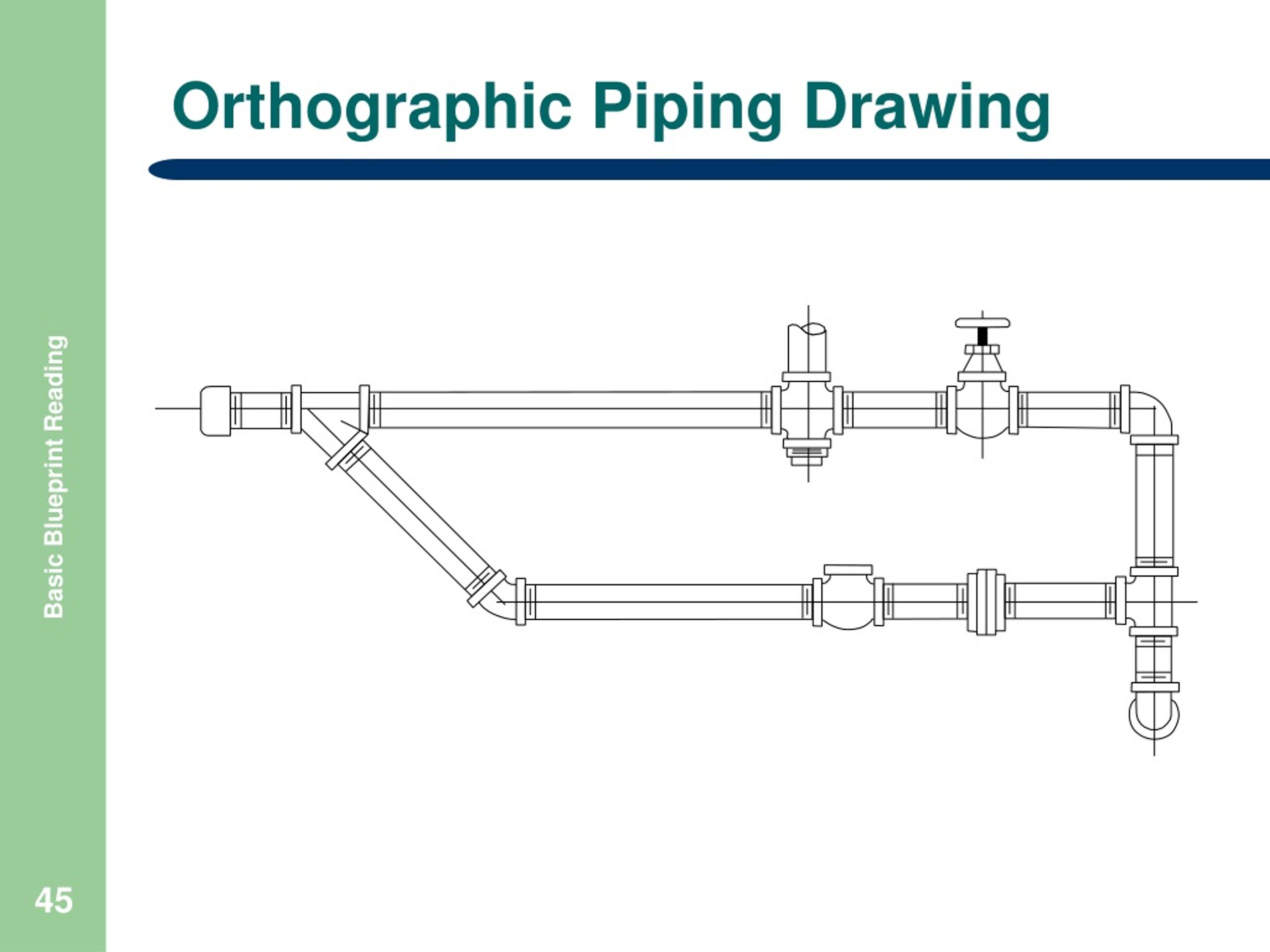
Piping orthographic drawing symbols kloology
Preparation & Design of Piping Engineering Drawings Itebs Academy
Checkout List Of Such Symbols Given Below.
Plan View At Different Elevations Are Prepared.
Web 42K Views 1 Year Ago Tutorials For Pipe Fitters And Fabricators.
Piping Fabrication Work Is Based On Isometric Drawings.
Related Post: