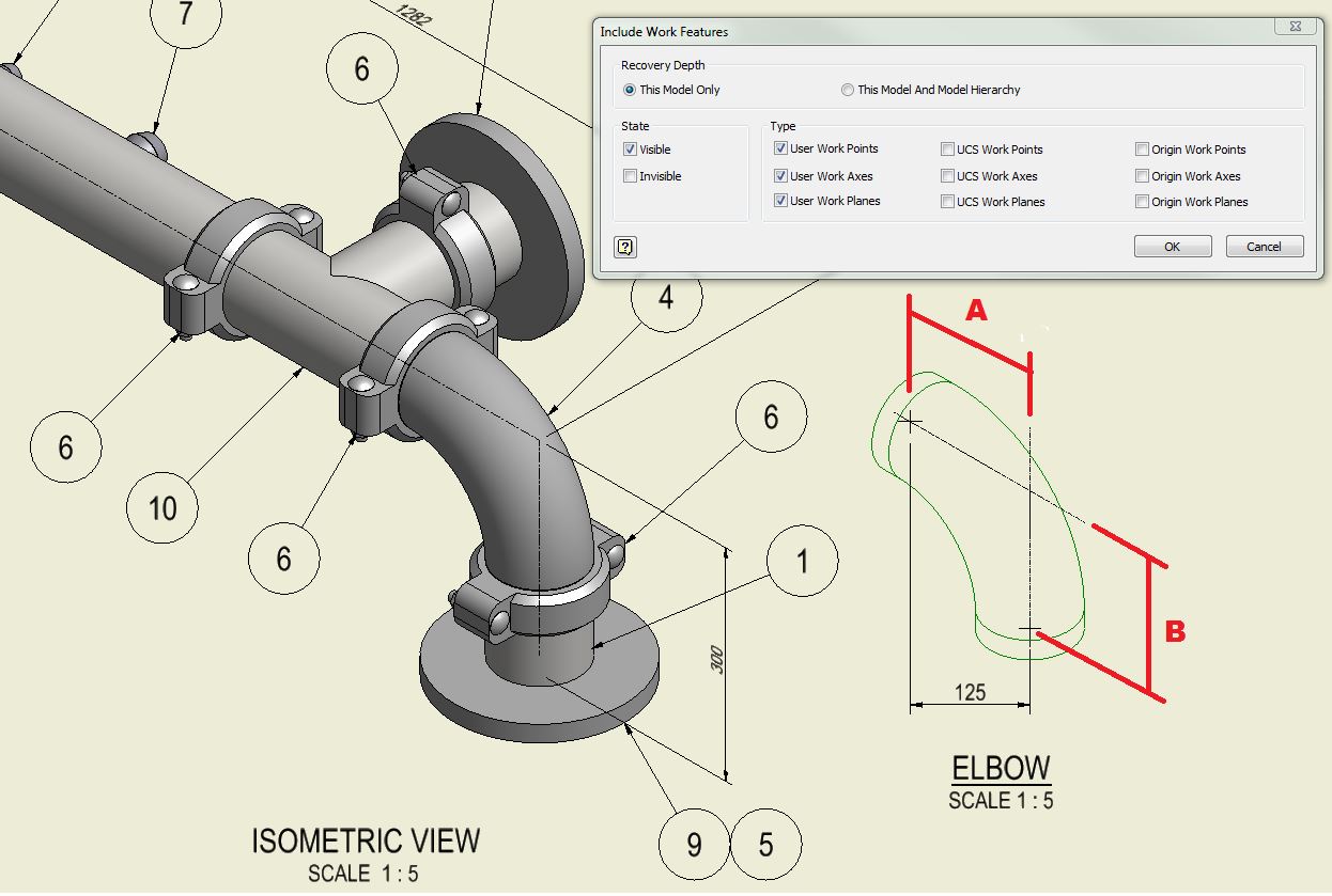
Piping Iso Drawing
Piping Iso Drawing - The symbols that represent fittings, valves and flanges are modified to adapt to the isometric grid. Web isometric drawings are, by definition, a visual depiction of a 3d routed line in a 2d plane that combines pipe height and length in a single drawing with a 30° angle on either side of the horizontal. Π x diameter of the. Automated bill of materials no more tedious material tracking when creating a pipe isometric drawing. Reading a piping isometric drawing basic training. Web a piping isometric drawing is a 2d drawing in which piping is represented like a 3d drawing. With the help of sophisticated computer aided design (cad) tools, piping engineers and designers can produce isometric drawings from 3d models with ease. Pipes are drawn with a single line irrespective of the line sizes, as well as the other configurations such as reducers,. By piping material group for purchasing materials by the construction, the team to erect the piping items on the site following proper routing. Web what is piping isometric drawings? Web what is piping isometric drawings? Web a piping isometric drawing is a technical drawing that depicts a pipe spool or a complete pipeline using an isometric representation. Web an isometric drawing is nothing but a detailed orthographic drawing that represents the details of 3d structure of the piping system in a 2d format. 3 clicks to draw a pipe,. Web m4 iso is the ideal tool for automatically generating unscaled piping isometric drawings from your 3d pipework models. Web this video explain about how to read piping isometric drawings before start the fabrication work?this channel explain about piping isometric,ndt,welding,cutt. By fabricator to fabricate the line. Main graphic section consist of isometric representation of a pipe line route in 3d. By piping material group for purchasing materials by the construction, the team to erect the piping items on the site following proper routing. Web the process of drafting isometric drawings for a pipeline system involves referencing the arrangements of the pipelines, sections, and elevation drawings during its development. The main body of an isometric piping drawing consists of the following:. Web what is piping isometric drawings? Web an isometric drawing is a type of pictorial drawing in which three sides of an object can be seen in one view. Isometric lines can be in vertical direction and two other directions at 30° from horizontal. Bottom section of isometric drawing contains:. With the help of sophisticated computer aided design (cad) tools,. The main purpose of an isometric is to provide all information necessary for the fabrication and erection along with the bill of material required to do so. Calculations for piping data from isometric drawing. The use of a north arrow in establishing pipe orientation and routing on the isometric is shown graphically. 3 clicks to draw a pipe, 3 clicks. Web draw piping isometrics efficiently. Web an explanation of how piping isometrics are created from plan and elevation views is explained. Web video tutorial on piping isometric drawing. Import idf or pcf files. Reading a piping isometric drawing basic training. Isometric lines can be in vertical direction and two other directions at 30° from horizontal. Web 42k views 1 year ago tutorials for pipe fitters and fabricators. Web here is an overview of the steps we need to take when creating iso pipe drawings: Web what is piping isometric drawings? It’s popular within the process piping industry because it can. Web isometric drawings are, by definition, a visual depiction of a 3d routed line in a 2d plane that combines pipe height and length in a single drawing with a 30° angle on either side of the horizontal. 3 clicks to draw a pipe, 3 clicks to add an elbow, 1 click to add a dimension and 3 clicks to. By fabricator to fabricate the line. Bottom section of isometric drawing contains:. Web draw piping isometrics efficiently. Web an isometric drawing is a type of pictorial drawing in which three sides of an object can be seen in one view. Unlike orthographics, piping isometrics allow the pipe to be drawn in a manner by which the length, width and depth. Calculations for piping data from isometric drawing. Pipes are shown in the same size. Web m4 iso is the ideal tool for automatically generating unscaled piping isometric drawings from your 3d pipework models. Web easy isometric is the first pipe isometric drawing app that helps users make detailed isometric drawings in the field and without the need for tedious reference. Web m4 iso is the ideal tool for automatically generating unscaled piping isometric drawings from your 3d pipework models. Π x diameter of the. Web easy isometric is the first pipe isometric drawing app that helps users make detailed isometric drawings in the field and without the need for tedious reference materials. Import idf or pcf files. Web the process of drafting isometric drawings for a pipeline system involves referencing the arrangements of the pipelines, sections, and elevation drawings during its development. The use of a north arrow in establishing pipe orientation and routing on the isometric is shown graphically. Web an isometric drawing is nothing but a detailed orthographic drawing that represents the details of 3d structure of the piping system in a 2d format. The main purpose of an isometric is to provide all information necessary for the fabrication and erection along with the bill of material required to do so. Web a piping isometric drawing includes information about the type of pipe, the diameter and thickness of the pipe, the location of valves, fittings, and other components, and the direction of flow. Main graphic section consist of isometric representation of a pipe line route in 3d space, which includes following information : Web an explanation of how piping isometrics are created from plan and elevation views is explained. Accurate drawing symbols, callouts, precise coordinates, and elevations provide intricate information to the fabricator. Web what is piping isometric drawings? Pipes are drawn with a single line irrespective of the line sizes, as well as the other configurations such as reducers,. Section of left or right of piping isometric drawing includes:. The main body of a piping isometric drawing is consist of:.
Learn isometric drawings (piping isometric)
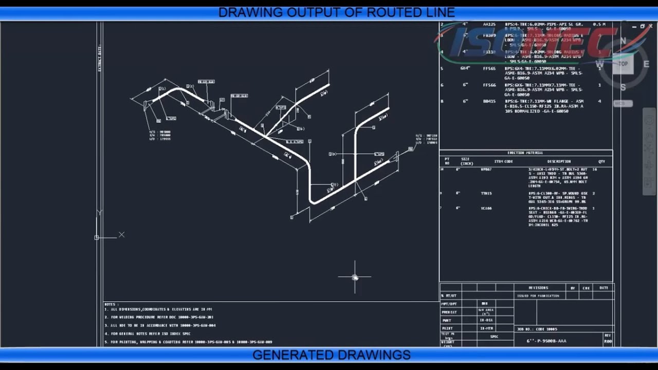
Piping Isometric Drawing at Explore collection of

Piping Design Basics Piping Isometric Drawings Piping Isometrics
PIPING ISO
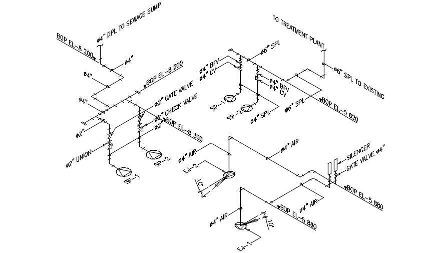
Piping isometric drawing examples planninglio
Piping Isometric Drawings Autodesk Community
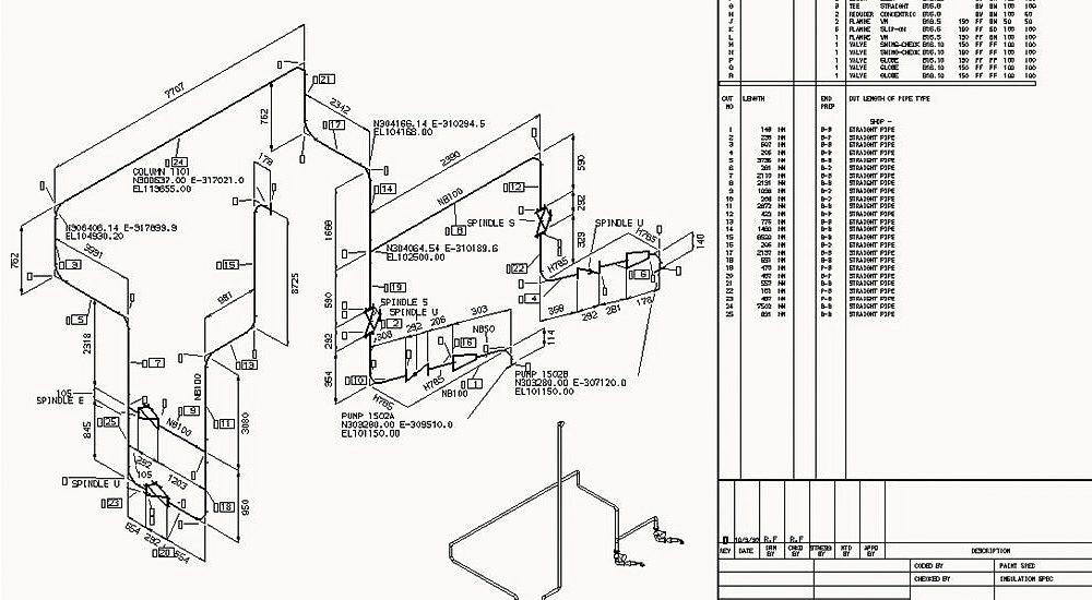
Automatic Piping Isometrics from 3D Piping Designs M4 ISO

Piping Isometric Drawing at Explore collection of
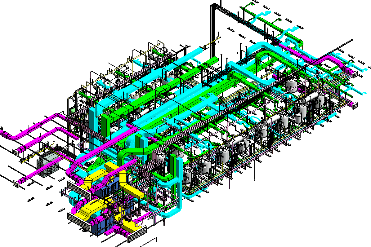
Revit AddOns EzISO Piping Models to Isometric Drawings

Isometric Piping Drawings Advenser
The Symbols That Represent Fittings, Valves And Flanges Are Modified To Adapt To The Isometric Grid.
Automated Bill Of Materials No More Tedious Material Tracking When Creating A Pipe Isometric Drawing.
The Fitting, Flange, And Valve Drawing Symbols Unique To Isometrics Are Depicted.
Web Video Tutorial On Piping Isometric Drawing.
Related Post:
