Pneumatic Drawing Symbols
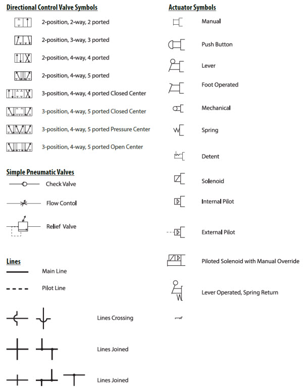
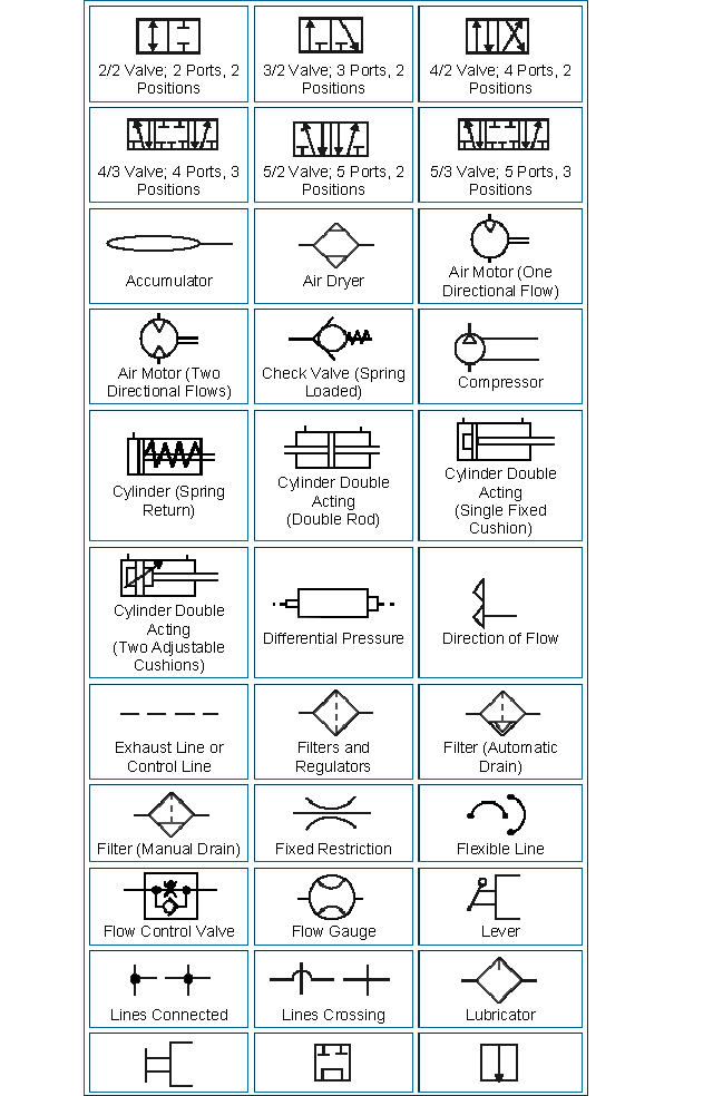
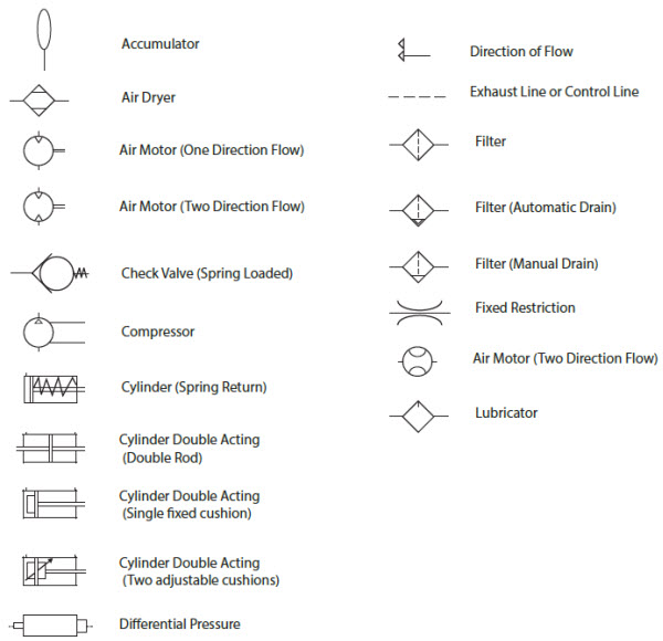
Pneumatic Drawing Symbols - To posltlon quick exhaust shuttle symbol description solenoid internal pilot supply reuote pilot supply md lot n and pilot or manual override pilot lines and functions description une dotted or line center line—. Web reading pneumatic schematic symbols the block the block symbolizes the possible valve functions or positions. These six basic valve symbols, when combined with the basic actuator symbols, comprise virtually all the directional valve symbols needed for air logic control. Web the first step in drawing a pneumatic circuit diagram is to familiarize yourself with the different standard symbols used to represent components like air sources, valves, actuators, accumulators, pressure regulators, and flow control devices. Here is a brief breakdown of how to read a symbol. The symbols shown below are generally based on. Accessory components are designed for a specific purpose. This type has an internal air pilot, and for the valve to open, compressed air pressure is needed at the inlet port (port 1). Which an iso or jis symbol does not exit. Web the symbols for these valve functions are shown in left graphic. With the new online release, it is easier than ever to draw your circuits. A 5/3 valve schematic will show three blocks describing 3 possible valve functions or positions. Directional air control valves are the building blocks of pneumatic control. Here is a brief breakdown of how to read a symbol. Web pneudraw allows you to draw pneumatic circuits quickly. Web the first step in drawing a pneumatic circuit diagram is to familiarize yourself with the different standard symbols used to represent components like air sources, valves, actuators, accumulators, pressure regulators, and flow control devices. Use the insert pneumatic component tool on the schematic tab insert components panel to insert your pneumatic symbols. They are commonly represented with symbols. Web. Accessory components are designed for a specific purpose. Web for additional information on pneumatic and hydraulic schematics click on the following links: These symbols needs to be understood before you can correctly interpret pneumatic drawings and diagrams. Which an iso or jis symbol does not exit. These are inlets, outlets and exhausts but excludes signal ports and external pilot feeds. The first numeral indicates the number of main ports. Symbols show the methods of actuation, the number of positions, the flow paths and the number of ports. This type has an internal air pilot, and for the valve to open, compressed air pressure is needed at the inlet port (port 1). These common symbols are shown below: Web reading pneumatic. The second numeral indicates the number of s t at es th e val ve can achi eve. This type has an internal air pilot, and for the valve to open, compressed air pressure is needed at the inlet port (port 1). Web pneumatic diagrams representing pneumatic systems have defined ways they are represented. Web pneumatic cylinder symbols. Accessory components. Web pneumatic cylinder symbols. These symbols needs to be understood before you can correctly interpret pneumatic drawings and diagrams. Symbols representing these valves provide a wealth of information about the valve they represent. A pneumatic motor or compressed air engine is a type of motor which does mechanical work by expanding compressed air. Web here are four simple circuits of. With the new online release, it is easier than ever to draw your circuits. Use the insert pneumatic component tool on the schematic tab insert components panel to insert your pneumatic symbols. Directional air control valves are the building blocks of pneumatic control. Accessory components are designed for a specific purpose. Symbols representing these valves provide a wealth of information. These six basic valve symbols, when combined with the basic actuator symbols, comprise virtually all the directional valve symbols needed for air logic control. Graphic symbols for pneumatic equipment. This is one standard identified by two numbers. Then use all of the autocad electrical toolset drafting and editing tools to modify the pneumatic layout, including stretch, trim and scoot. Here. They are commonly represented with symbols. These common symbols are shown below: Web the symbols for these valve functions are shown in left graphic. Symbols show the methods of actuation, the number of positions, the flow paths and the number of ports. The first numeral indicates the number of main ports. Web the symbols for these valve functions are shown in left graphic. Web the first step in drawing a pneumatic circuit diagram is to familiarize yourself with the different standard symbols used to represent components like air sources, valves, actuators, accumulators, pressure regulators, and flow control devices. Here is a brief breakdown of how to read a symbol. These are. Web all the symbols you need to design your pneumatic circuit in.dxf format. Web practicalguide pneumatics pneumatics t contents 2 cha 2 pneuma circ s e cha 6 pneumatic t hose cha 4 pneuma actuat (a c asics cha 9 electr pneuma syst action cha 12 pneuma actuat vs electromechanical cha 3 u pneuma a preparation cha 8 ar pneumatic components compatibl9 cha 11 ener e˜cien pneuma systems cha 5 valv. The symbols shown below are generally based on. These are inlets, outlets and exhausts but excludes signal ports and external pilot feeds. Web here are four simple circuits of pneumatic components that can be used alone or as building blocks in larger systems. Symbols show the methods of actuation, the number of positions, the flow paths and the number of ports. Web pneudraw allows you to draw pneumatic circuits quickly and easily. Symbols show the methods of actuation, the number of positions, the flow paths and the number of ports. Web what are pneumatic circuit symbols & what are they used for? Web reading pneumatic schematic symbols the block the block symbolizes the possible valve functions or positions. Web symbols used in pneumatic / hydraulic circuit diagrams. These symbols needs to be understood before you can correctly interpret pneumatic drawings and diagrams. They are commonly represented with symbols. With the new online release, it is easier than ever to draw your circuits. Directional air control valves are the building blocks of pneumatic control. A practical guide to pneumatics is a good place to
Autocad pneumatic symbols peplm

Pneumatic Symbols explained Pneumatics & Sensors Ireland
Pneumatics Chart AutomationPrimer

Pneumatic Symbols explained Pneumatics & Sensors Ireland

Hydraulics and Pneumatics Technical Training Pert Industrials
Pneumatic Circuit Symbols Explained

Pneumatic Symbols explained Pneumatics & Sensors Ireland
Pneumatics Banff Academy Technological Studies 07
Pneumatic Circuit Symbols Explained

Pneumatic Symbols explained Pneumatics & Sensors Ireland
Circuit Symbols Are Used Through This Catalogue And On The Labels Of Most The Situation Also Occurs When Smc Develop New Product Systems For Smc Pneumatic Products.
Web The Function Of A Valve Is Given By A Pair Of Numera L S Separat Ed B Y A St Rok E, E.g.
A 5/2 Valve Schematic Will Be Illustrated With 2 Blocks Describing Two Valve Functions Or Positions.
Graphic Symbols For Pneumatic Equipment.
Related Post:
