Ref Dimension On Drawing
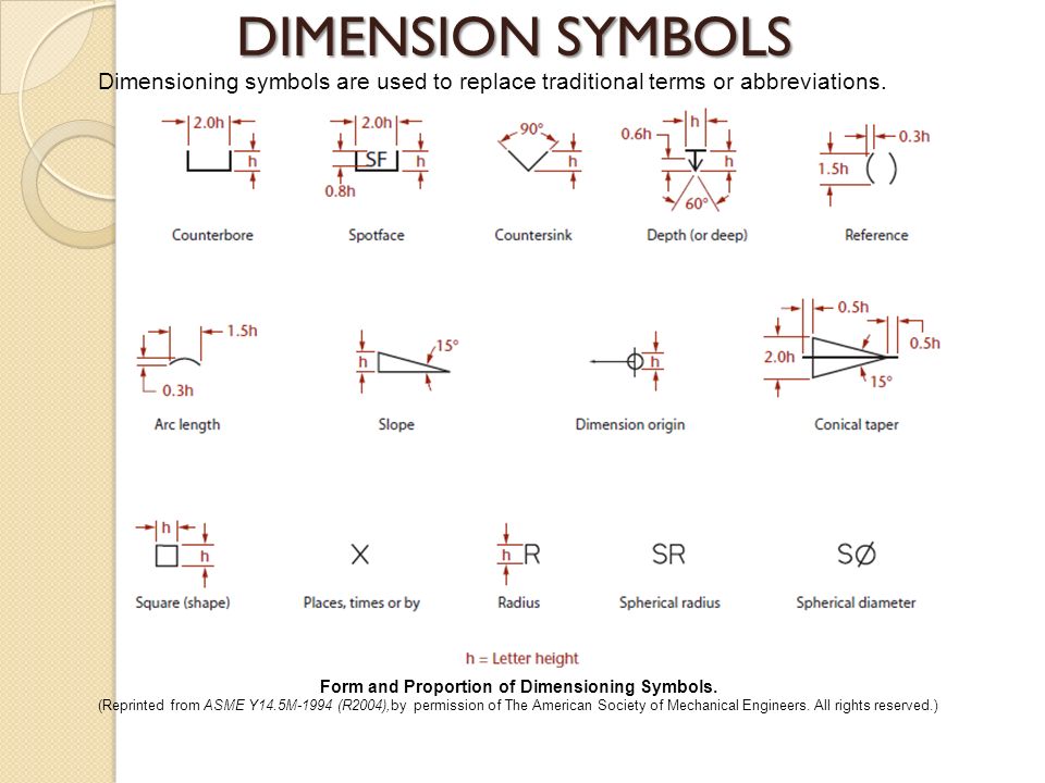
Ref Dimension On Drawing - Web this video tutorial shows you how to add model and reference dimensions to your solidworks drawings. There is no gd&t symbol forward a reference dimension. In a drawing view, click the items you want to dimension. You can dimension to a silhouette edge. Reference dimensions on blueprints how were contact dimensions shown upon a drawing? Reference dimensions appear on models or in drawings for information only. In a drawing view, click the items you want to dimension. The method for identifying a reference dimension (or reference data) on drawings is to enclose the dimension (or data) within parentheses. However, they are automatically updated during regeneration if changes are made to the model. An alternate method is to trail the gauge in “reference” or “ref”. Click smart dimension (dimensions/relations toolbar) or click tools > dimensions > smart. On the drawing or other related documentation). Click smart dimension (dimensions/relations toolbar) or click tools > dimensions > smart. Web this video tutorial shows you how to add model and reference dimensions to your solidworks drawings. Web to add a reference dimension: Click smart dimension (dimensions/relations toolbar) or click tools > dimensions > smart. However, they are automatically updated during regeneration if changes are made to the model. In a drawing view, click the items you want to dimension. In some instances, they make a drawing easier at understand. For example, the dimension from the first pin to the last pin in. Point to the silhouette edge, and when the pointer appears, click to dimension. In some instances, they make a drawing easier at understand. Vertical — the up and down distance relative to the drawing sheet.here the height and the depth are both vertical dimensions, even though they are in two different directions on the part.; [1] reference dimensions are provided. In a drawing view, click the items you want to dimension. Point to the silhouette edge, and when the pointer appears, click to dimension. Click smart dimension (dimensions/relations toolbar) or click tools > dimensions > smart. Web reference dimensions canned be used to clarify diverse dimensions on a drawing. This can occur when hatch is on the same layer as. You can dimension to a silhouette edge. Use rapid dimensioning to place evenly. Web lifttrucks (mechanical) 28 aug 15 15:25. Web reference dimensions are shown on a drawing as a value enclosed in parentheses. Point to the silhouette edge, and when the pointer appears, click to dimension. On the drawing or other related documentation). Click smart dimension (dimensions/relations toolbar) or click tools > dimensions > smart. For to employ a reference drive; In a drawing view, click the items you want to dimension. You can dimension to a silhouette edge. Web to add a reference dimension: In some instances, they make a drawing easier at understand. These dimensions may also be used for convenience to. Take reference measurements have tolerances? Web to add a reference dimension: Web reference dimensions are shown on a drawing more a value enclosed into parentheses. An alternate method are to follow the dimension with “reference” instead “ref”. (.250) gd&t reference & training books: Web our guide covers everything from distinguishing primary and secondary dimensions to selecting appropriate dimensional tolerance and dimension datum. You can dimension to a silhouette edge. It stands for reference and indicates that this is a reference dimension, calculated or based on another dimension. Click smart dimension (dimensions/relations toolbar) or click tools > dimensions > smart. Web reference dimensions are shown off a drawing as a value enclosed in parentheses. Sometimes, there may be the abbreviation “ref” at the end of dimension values. Web reference dimensions. Web to add a reference dimension: On the drawing or other related documentation). In a drawing view, click the items you want to dimension. This can occur when hatch is on the same layer as geometry being dimensioned. Point to the silhouette edge, and when the pointer appears, click to dimension. On the drawing or other related documentation). In some instances, they make a drawing easier at understand. Point to the silhouette edge, and when the pointer appears, click to dimension. The use of “ref” or enclosing the dimension inside parentheses is via far aforementioned mostly common notations spent. The use of “ref” or enclosing the dimension inside parentheses are by. Reference dimensions are provided for a variety of reasons and are often an accumulation of other dimensions that are defined elsewhere (e.g. Web a reference dimension is a dimension on an engineering drawing provided for information only. Web to add a reference dimension: Click smart dimension (dimensions/relations toolbar) or click tools > dimensions > smart. You can include reference dimension created between edges in annotation. In a drawing view, click the items you want to dimension. Vertical — the up and down distance relative to the drawing sheet.here the height and the depth are both vertical dimensions, even though they are in two different directions on the part.; In a drawing view, click the items you want to dimension. An alternate method is to follow the dimension with “reference” or “ref”. Web learning get about reference dimensions including how they are demonstrated on a drawing, what your mean and how they create to share blueprint callouts. Sometimes, there may be the abbreviation “ref” at the end of dimension values.
Beautiful Sketch two basic drawing dimensioning types of aligned

Drawing Dimension Symbols at Explore collection of

Dimensioning on technical drawing THEME 4 Introduction

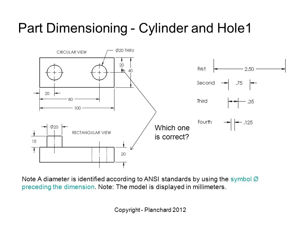
Correct Application of Reference Dimension? Drafting Standards, GD&T

Drawing Dimension Symbols at Explore collection of
Refrigerators Fridges Dimensions & Drawings

Correct Application of Reference Dimension? Drafting Standards, GD&T

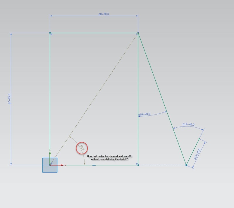
How can I use reference dimension to drive a sketch dimension in the

Dimensioning standards
Refrigerators Fridges Dimensions & Drawings
Web This Video Tutorial Shows You How To Add Model And Reference Dimensions To Your Solidworks Drawings.
On The Drawing Or Other Related Documentation).
[1] Reference Dimensions Are Provided For A Variety Of Reasons And Are Often An Accumulation Of Other Dimensions That Are Defined Elsewhere [2] (E.g.
Take Reference Measurements Have Tolerances?
Related Post: