Section Line In Engineering Drawing
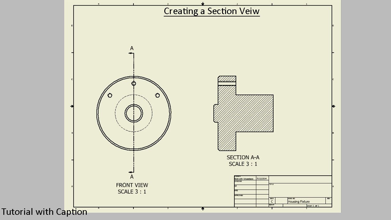
Section Line In Engineering Drawing - All the visible edges behind the cutting plane should be shown. For large parts, outline sectioning may be used to save time. Web the selection of the width of the line depends on the scale, size, and type of the drawing. These lines are typically represented by using hatching and can be used to represent various features of an object, such as angles, dimensions, and surfaces. Convert the section to 2d view if you wish (using the tools in your cad software). Web the surface of the imaginary cut is crosshatched with lines called section lines. Hidden lines are light, dashed, narrow, and short. Web the cut surfaces are identified by drawing section lines and the view thus obtained is called the “sectional view” or “view in section” of the remaining object. Engineering drawings use standardised language and symbols. Web types of lines for technical drawings visible lines. Web the section lines should be evenly spaced and of equal thickness, and should be thinner than visible lines also, do not run section lines beyond the visible outlines or stop them too short object lines in the section view. Notice that the square hole in the object has no section lining, since it was not changed by sectioning. A. Web a section or cross section is a view generated from a part or assembly on a cutting plane or multiple cutting planes that reveals the outlines on the inside or assembly fits. Web an engineering drawing is a subcategory of technical drawings. Web the cut surfaces are identified by drawing section lines and the view thus obtained is called. Phantom lines are used to represent a movable feature in its different positions. 0.13 mm, 0.18mm, 0.25 mm, 0.35 mm, 0.50mm, 0.70mm, 1.0mm, 1.4 mm, and 2.0 mm. The width of the line should be chosen from one of the following. Web sectioning in technical drawing involves the use of cutting lines, section lines, and section symbols. Engineering drawings use. Web an engineering drawing is a subcategory of technical drawings. Web an engineering drawing is a type of technical drawing that is used to convey information about an object. The spacing of section lines is equal or uniform on a section view. The lines in the figure above, which look like saw marks, are called section lining. These are used. The spacing of section lines is equal or uniform on a section view. Web section lines are generally drawn at a 45° angle. “sketching” generally means freehand drawing. Hidden lines are almost never shown on section views. Rules of sectioning rule 1: All the visible edges behind the cutting plane should be shown. Web how to improve your section drawings lineweights. The width of the line should be chosen from one of the following. Half section a half section view means that you are only removing a quarter of an object. Web the cut surfaces are identified by drawing section lines and. For most purposes, the general use symbol of cast iron is used. The purpose is to convey all the information necessary for manufacturing a product or a part. Web following are the different types of lines used in engineering drawing: Web section lining is a method of representing internal features of an object in an engineering drawing. The lines in. Generally, lines of three different widths. For large parts, outline sectioning may be used to save time. Web sectioning in technical drawing involves the use of cutting lines, section lines, and section symbols. Gasket is drawn solid black to show that it is sectioned Notice that the square hole in the object has no section lining, since it was not. Web we will treat “sketching” and “drawing” as one. Also known as object lines, visible. “sketching” generally means freehand drawing. Web the selection of the width of the line depends on the scale, size, and type of the drawing. To begin, draw a cutting line across the object you want to section. Web the selection of the width of the line depends on the scale, size, and type of the drawing. Web we will treat “sketching” and “drawing” as one. Web section lines and symbols. A section lined area is always completely bounded by a visible outline. Web and this is my friend, how you create a section view on the engineering. Web section lining is a method of representing internal features of an object in an engineering drawing. Section lines shown in opposite directions indicate a different part. Generally, lines of three different widths. Also known as object lines, visible. Next, draw two section lines that start and end on the cutting line. This type of view is ordinarily used when the object is symmetrical or if you only need to show a portion of a complex assembly. They provide features that can not be seen in a. Web sectioning in technical drawing involves the use of cutting lines, section lines, and section symbols. Convert the section to 2d view if you wish (using the tools in your cad software). Web the section lines should be evenly spaced and of equal thickness, and should be thinner than visible lines also, do not run section lines beyond the visible outlines or stop them too short object lines in the section view. Textures can provide a touch of realism to section drawings. Gasket is drawn solid black to show that it is sectioned The series is based on the common ratio of 1:√2 or 1:1.4. Web following are the different types of lines used in engineering drawing: A common use is to specify the geometry necessary for the construction of a component and is called a detail drawing. Web types of lines in engineering drawing:
Full Sectioning Problem 2 Engineering Drawing 9.2 YouTube

SECTION DRAWINGS BRANDON OWENS' PORTFOLIO
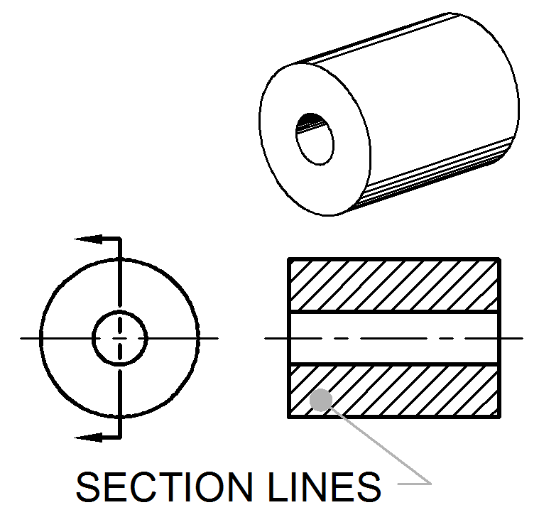
Section Lines ToolNotes

Sectional Views
Sectional View Engineering Drawing Exercises at GetDrawings Free download
Engineering Drawing Tutorials/Orthographic and sectional views ( T 11.2

Engineering Drawing Tutorials/Orthographic and sectional views ( T 11
Engineering Drawing Tutorials/Orthographic and sectional views ( T 11.1
Sectioning Technique Engineering Design McGill University

SECTION DRAWINGS BRANDON OWENS' PORTFOLIO
Web We Will Treat “Sketching” And “Drawing” As One.
Click The 'Create Section' Tool In Your Cad Software, And The Object Will Be Sectioned:
All The Visible Edges Behind The Cutting Plane Should Be Shown.
The Spacing Of Section Lines Is Equal Or Uniform On A Section View.
Related Post: