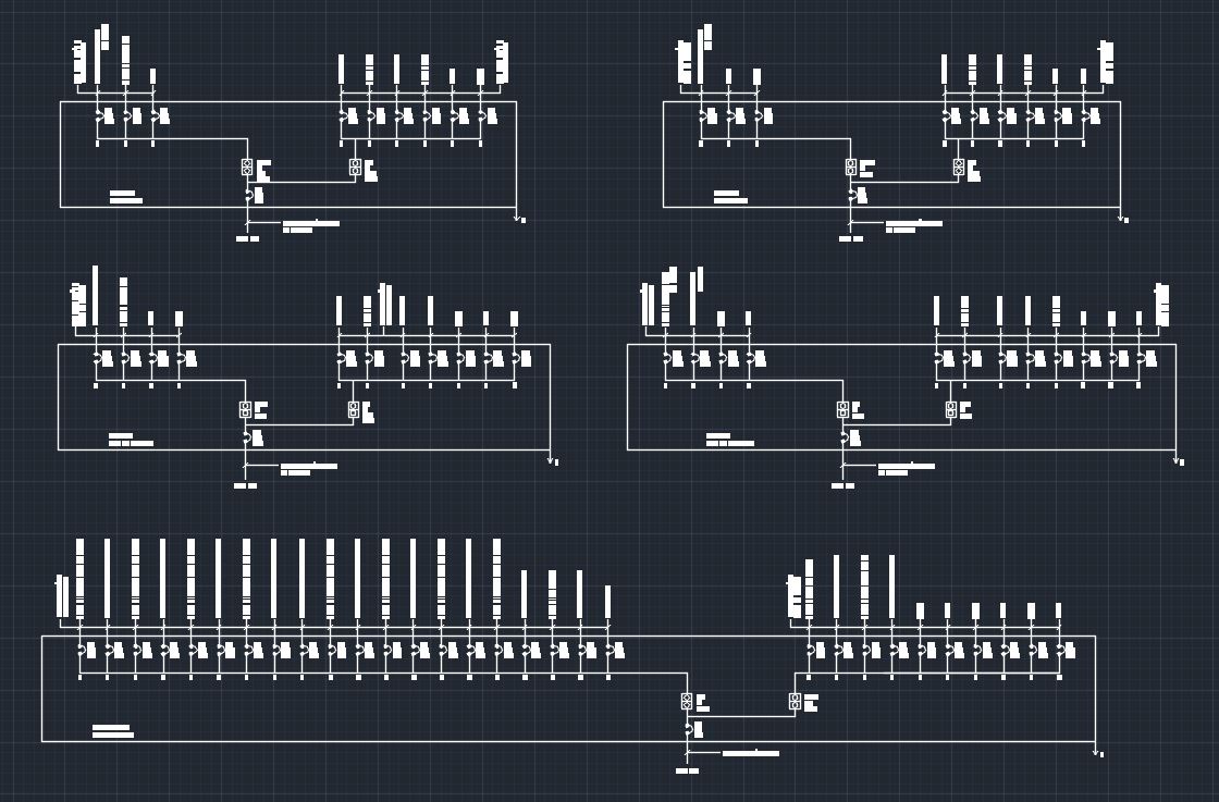
Single Line Drawing Electrical
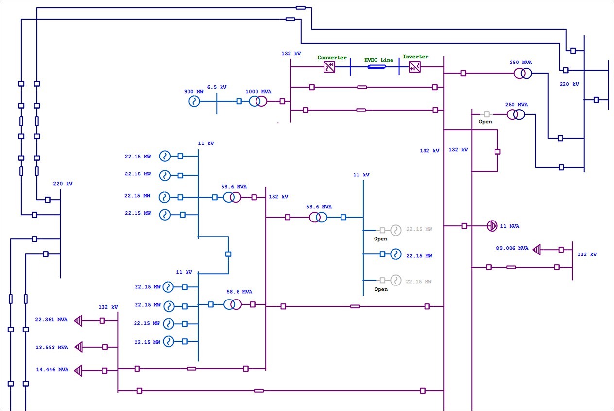
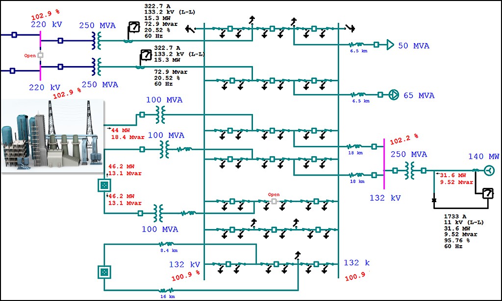
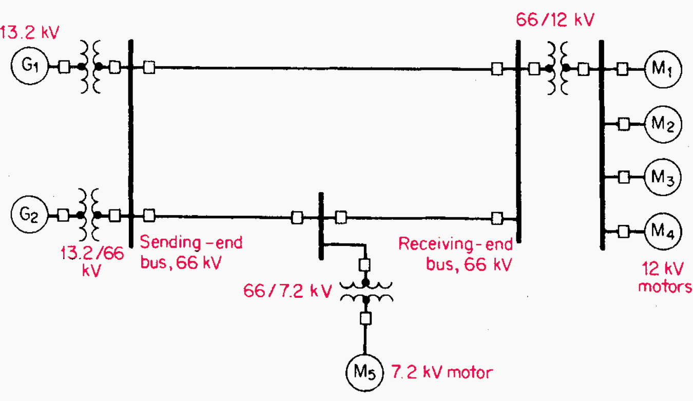
Single Line Drawing Electrical - It is a graphical representation of a circuit or system using standard electrical symbols. In figure 1 main low voltage distribution board consisted of five sections, i.e. Web in electrical engineering, a single line diagram is a simplified representation of an electrical power system or electrical grid that shows the flow of electricity through the system. Serving as a map of the electrical distribution system in a facility, an sld documents conductors, transformers, overcurrent protective devices (ocpds) and other. Diagrams start at the top of the page with the incoming source of a system’s power. Just keep in mind that although some single line diagrams may appear overwhelming by virtue of their size and the wide variety of equipment represented, they can all be. This condenses the space and complexity of the diagram for simpler troubleshooting. Web example of single line diagram. Web the single line diagram is the first step in preparing a critical response plan, allowing you to become thoroughly familiar with the electrical system. Dashed rectangles are most often. Cubicles, is shown in the form of single line diagram (sld). Just keep in mind that although some single line diagrams may appear overwhelming by virtue of their size and the wide variety of equipment represented, they can all be. Main components such as transformers, switches, and breakers are indicated by their standard graphic symbol. Serving as a map of. Web in electrical engineering, a single line diagram is a simplified representation of an electrical power system or electrical grid that shows the flow of electricity through the system. Dashed rectangles are most often. It is a graphical representation of a circuit or system using standard electrical symbols. Just keep in mind that although some single line diagrams may appear. Web in electrical engineering, a single line diagram is a simplified representation of an electrical power system or electrical grid that shows the flow of electricity through the system. Web electrical one line diagram design. Remember that you are using a single line to represent multiple conductors. This condenses the space and complexity of the diagram for simpler troubleshooting. Just. Cubicles, is shown in the form of single line diagram (sld). These diagrams are used in designing, operating and maintaining. It is a graphical representation of a circuit or system using standard electrical symbols. Diagrams start at the top of the page with the incoming source of a system’s power. Serving as a map of the electrical distribution system in. Web in electrical engineering, a single line diagram is a simplified representation of an electrical power system or electrical grid that shows the flow of electricity through the system. Remember that you are using a single line to represent multiple conductors. This condenses the space and complexity of the diagram for simpler troubleshooting. It is a graphical representation of a. Serving as a map of the electrical distribution system in a facility, an sld documents conductors, transformers, overcurrent protective devices (ocpds) and other. Main components such as transformers, switches, and breakers are indicated by their standard graphic symbol. Diagrams start at the top of the page with the incoming source of a system’s power. Just keep in mind that although. Main components such as transformers, switches, and breakers are indicated by their standard graphic symbol. Dashed rectangles are most often. Web electrical one line diagram design. Cubicles, is shown in the form of single line diagram (sld). It is a graphical representation of a circuit or system using standard electrical symbols. It is a graphical representation of a circuit or system using standard electrical symbols. Web electrical one line diagram design. Cubicles, is shown in the form of single line diagram (sld). This condenses the space and complexity of the diagram for simpler troubleshooting. Main components such as transformers, switches, and breakers are indicated by their standard graphic symbol. Remember that you are using a single line to represent multiple conductors. Web electrical one line diagram design. This condenses the space and complexity of the diagram for simpler troubleshooting. Web in electrical engineering, a single line diagram is a simplified representation of an electrical power system or electrical grid that shows the flow of electricity through the system. In. Web electrical one line diagram design. Web example of single line diagram. These diagrams are used in designing, operating and maintaining. This condenses the space and complexity of the diagram for simpler troubleshooting. Web the single line diagram is the first step in preparing a critical response plan, allowing you to become thoroughly familiar with the electrical system. Web the single line diagram is the first step in preparing a critical response plan, allowing you to become thoroughly familiar with the electrical system. These diagrams are used in designing, operating and maintaining. Web in electrical engineering, a single line diagram is a simplified representation of an electrical power system or electrical grid that shows the flow of electricity through the system. Dashed rectangles are most often. Main components such as transformers, switches, and breakers are indicated by their standard graphic symbol. Web example of single line diagram. Remember that you are using a single line to represent multiple conductors. Cubicles, is shown in the form of single line diagram (sld). In figure 1 main low voltage distribution board consisted of five sections, i.e. This condenses the space and complexity of the diagram for simpler troubleshooting. Serving as a map of the electrical distribution system in a facility, an sld documents conductors, transformers, overcurrent protective devices (ocpds) and other. It is a graphical representation of a circuit or system using standard electrical symbols.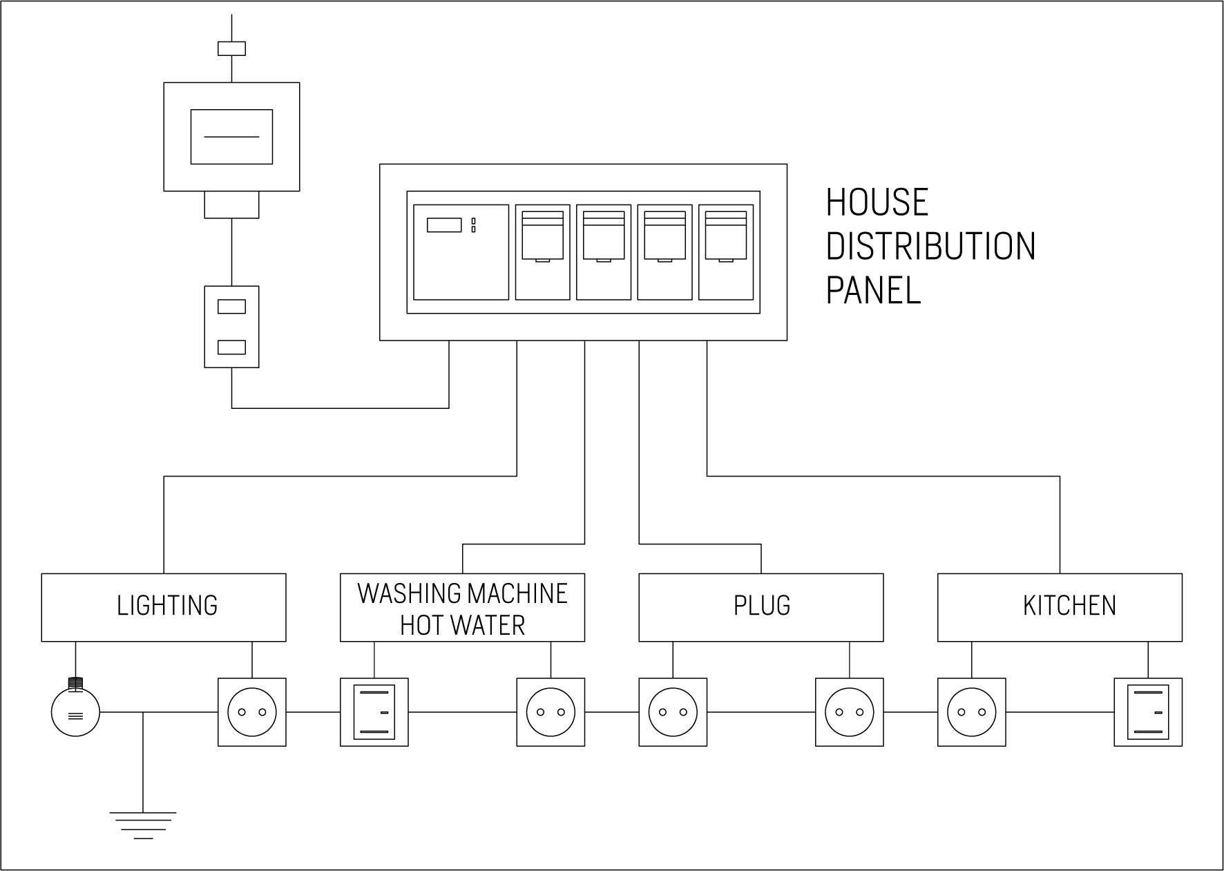
Single Line Diagram Of Electrical House Wiring Wiring Diagram and

How To Calculate and Draw a Single Line Diagram For The Power System EEP
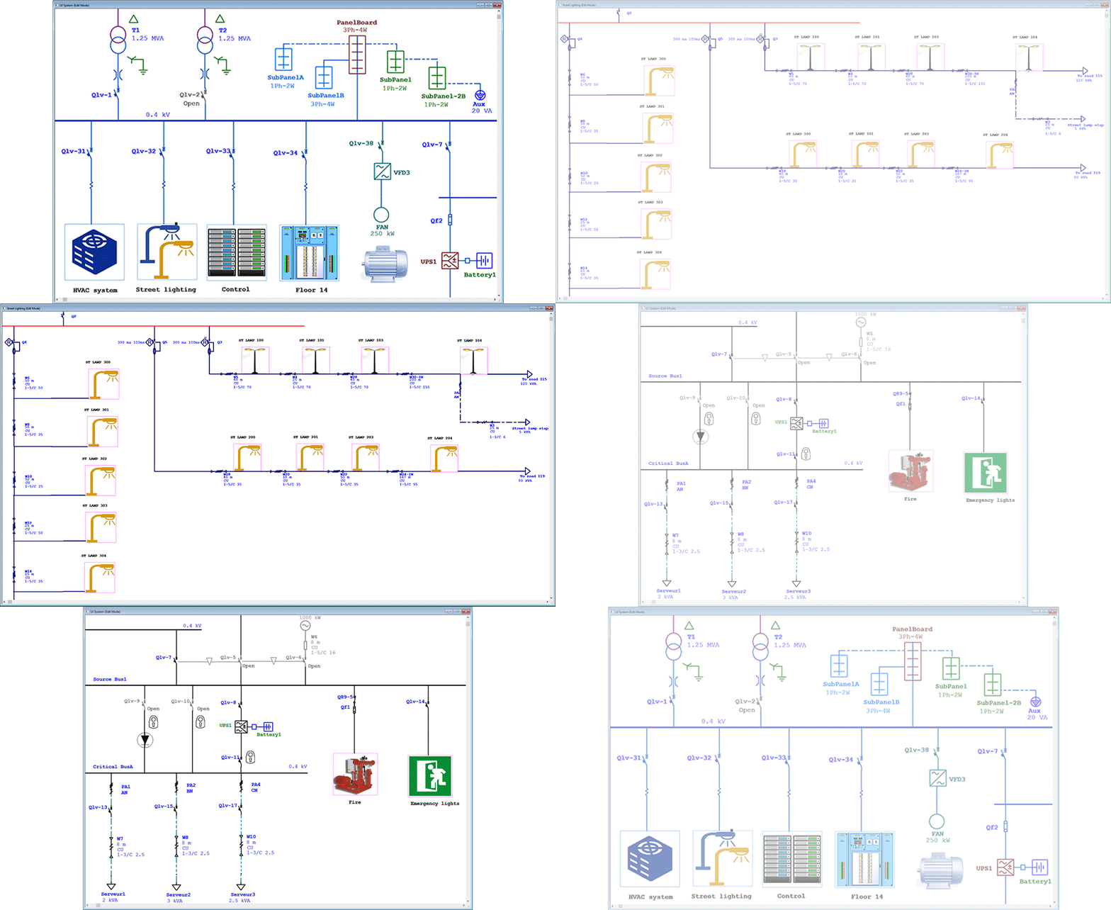
Electrical SingleLine Diagram Intelligent One Line Diagram ETAP
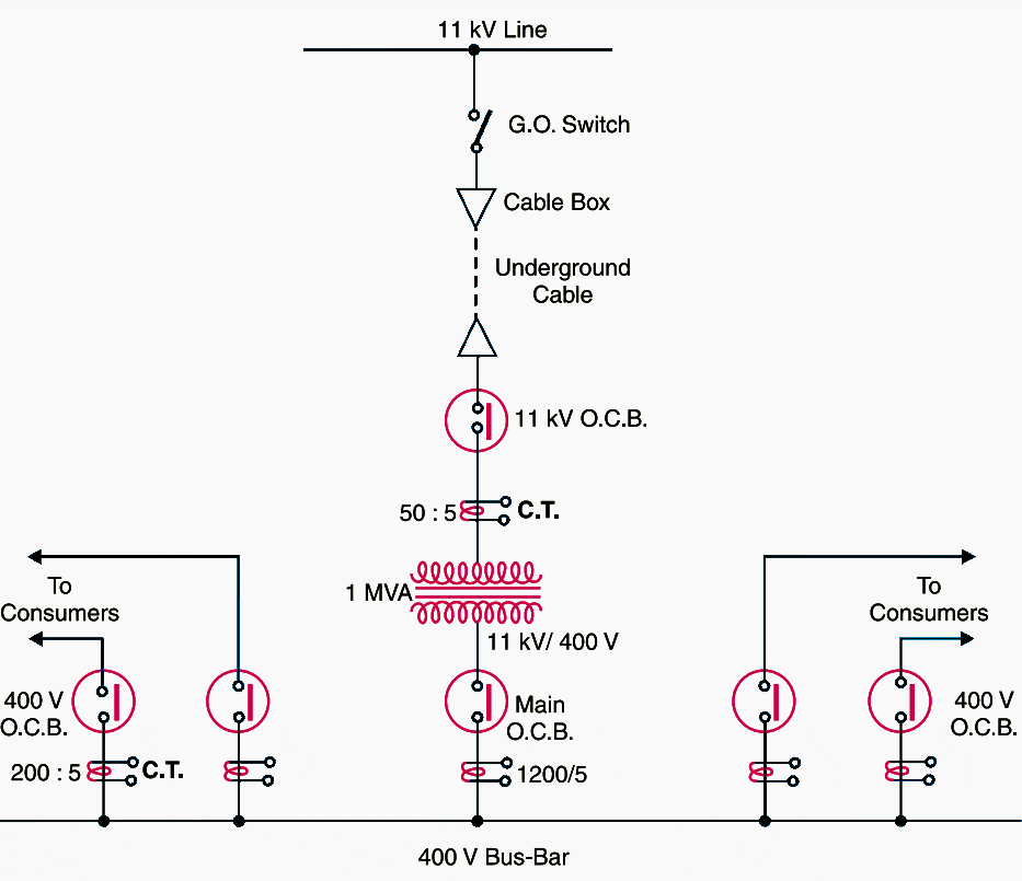
Single line diagrams of substations 66/11 kV and 11/0.4 kV EEP
Electrical SingleLine Diagram Electrical OneLine Diagram ETAP

Electrical Diagrams and Schematics Inst Tools
Electrical SingleLine Diagram Electrical OneLine Diagram ETAP
Electrical Single Line Diagram Template (DWG) — LINE DRAW CAD LAB

Single Line Diagram of Power Plant Power Systems
How To Calculate and Draw a Single Line Diagram For The Power System EEP
Web Electrical One Line Diagram Design.
Diagrams Start At The Top Of The Page With The Incoming Source Of A System’s Power.
Just Keep In Mind That Although Some Single Line Diagrams May Appear Overwhelming By Virtue Of Their Size And The Wide Variety Of Equipment Represented, They Can All Be.
Related Post:
