Start Stop Circuit Drawing
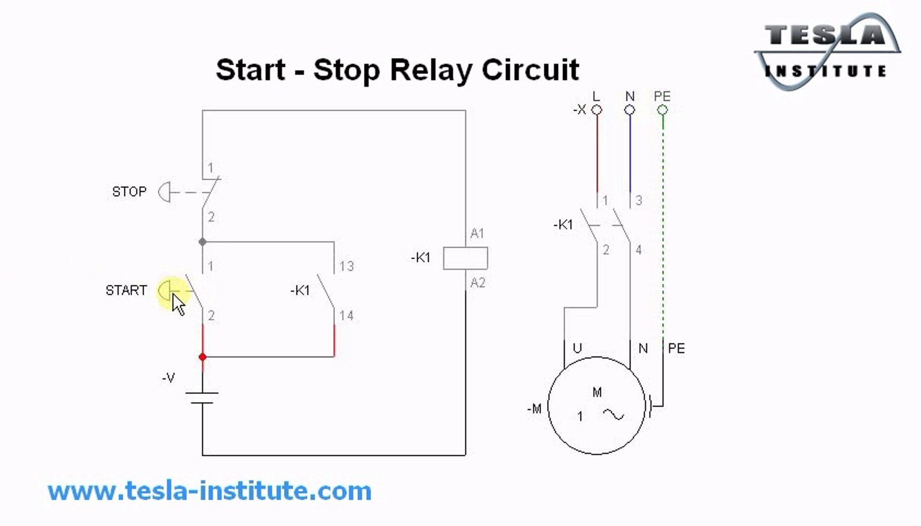
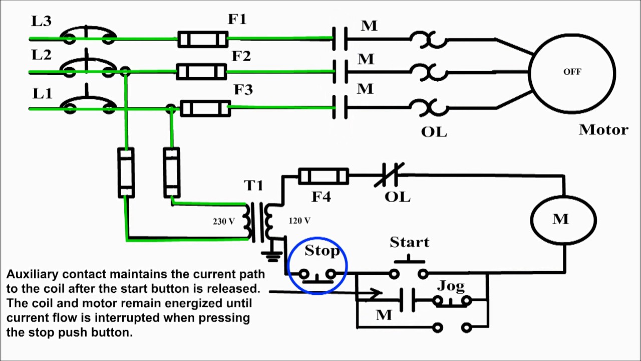
Start Stop Circuit Drawing - When the state switch is open, the motor will not work. Web the basic language of control is the circuit diagram. This pattern is an extension to the sealed in coil pattern and is similar to the state coil. These components include a power supply, a push button switch, a relay, a diode, and resistors. The blue lines in the circuit diagram represent the current flow. The control circuit (start stop) tells a motor or electrical component when to run and stop. As long as you follow the ladder diagram and take it one wire at a time its simple.this. In fact, you can use them in motors as well. Specify how many buttons of each type are required in your circuit: When the button is released, the circuit to the coil is opened and then remakes the. It shows the various components and their connections, allowing for easy understanding and troubleshooting of the circuit. This diagram showcases how power flows through the control circuit to start and stop the motor, providing a clear understanding of its operation and configuration. Starting a three phase motor. Enter the numbers you require then click ok. The trigger condition takes priority. While selecting of mccb just short circuit and over current protection is enough to this application. These components include a power supply, a push button switch, a relay, a diode, and resistors. Web basic motor control: Starting a three phase motor. Web exploring the complete diagram and instructions for building the circuit. Start stop motor control circiuit and wiring installation.part two.more. Web in its normal position the circuit operates as a simple stop/start control. Web start stop circuits are used on pieces of equipment and machinery that feature electrical motors and control circuits. The trigger condition takes priority over the break condition), the start/stop circuit is “stop dominant”: Web motor starter schematic. In fact, you can use them in motors as well. The complete diagram of the one push button start stop circuit includes several components that are essential for its functioning. Circuit diagram this diagram is the most basic circuit that uses a switch to control a motor through a contactor. The trigger condition takes priority over the break condition), the. In fact, you can use them in motors as well. Starting a three phase motor. Start stop motor control circiuit and wiring installation.part two.more. As long as you follow the ladder diagram and take it one wire at a time its simple.this. Start stop motor control circiuit and wiring. Start stop motor control circiuit and wiring installation.part two.more. In fact, you can use them in motors as well. This diagram showcases how power flows through the control circuit to start and stop the motor, providing a clear understanding of its operation and configuration. Web motor starter schematic and wiring diagram. These components include a power supply, a push button. Start stop motor control circiuit and wiring installation.part two.more. Enter the numbers you require then click ok. The blue lines in the circuit diagram represent the current flow. While the jogging button is pressed, coil k1.4 is energized. Web basic motor control: They could be any of the preceding or following circuits that provide undervoltage protection. Specify how many buttons of each type are required in your circuit: Td03309004e for more information visit: Web exploring the complete diagram and instructions for building the circuit. The blue lines in the circuit diagram represent the current flow. Web a start stop schematic diagram is a graphical representation of the electrical circuit used to control the start and stop operation of electric motors or other devices. The trigger condition takes priority over the break condition), the start/stop circuit is “stop dominant”: Circuit breaker (cb), magnetic starter, thermal relay. 35k views 2 years ago. Start stop motor control circiuit. Circuit diagram this diagram is the most basic circuit that uses a switch to control a motor through a contactor. Web basic motor control: Start stop motor control circiuit and wiring. The control circuit (start stop) tells a motor or electrical component when to run and stop. Start stop motor control circiuit and wiring installation.part two.more. When the button is released, the circuit to the coil is opened and then remakes the. Web motor starter schematic and wiring diagram. Web start stop circuits are used on pieces of equipment and machinery that feature electrical motors and control circuits. Starting a three phase motor. The voltage level of the control circuit can vary from 24v to 400v or more, but 24 volts is typically used for the control side. Start stop 3 wire control. These components include a power supply, a push button switch, a relay, a diode, and resistors. The coil can only be energized with the start pushbutton and only for a length of time that the button is pressed. 3 wire start stop circuit. Web the basic language of control is the circuit diagram. 35k views 2 years ago. Circuit diagram this diagram is the most basic circuit that uses a switch to control a motor through a contactor. This diagram showcases how power flows through the control circuit to start and stop the motor, providing a clear understanding of its operation and configuration. Web a start stop schematic diagram is a graphical representation of the electrical circuit used to control the start and stop operation of electric motors or other devices. While the jogging button is pressed, coil k1.4 is energized. In fact, you can use them in motors as well.
Simple Start Stop Wiring Diagram
Simple Start Stop Circuit Diagram
Basic Start Stop Circuit Diagram
Basic Start Stop Wiring Diagram
basic start stop circuit diagram
Startstop Circuits Everything You Need To Know
Simple Start Stop Circuit Diagram
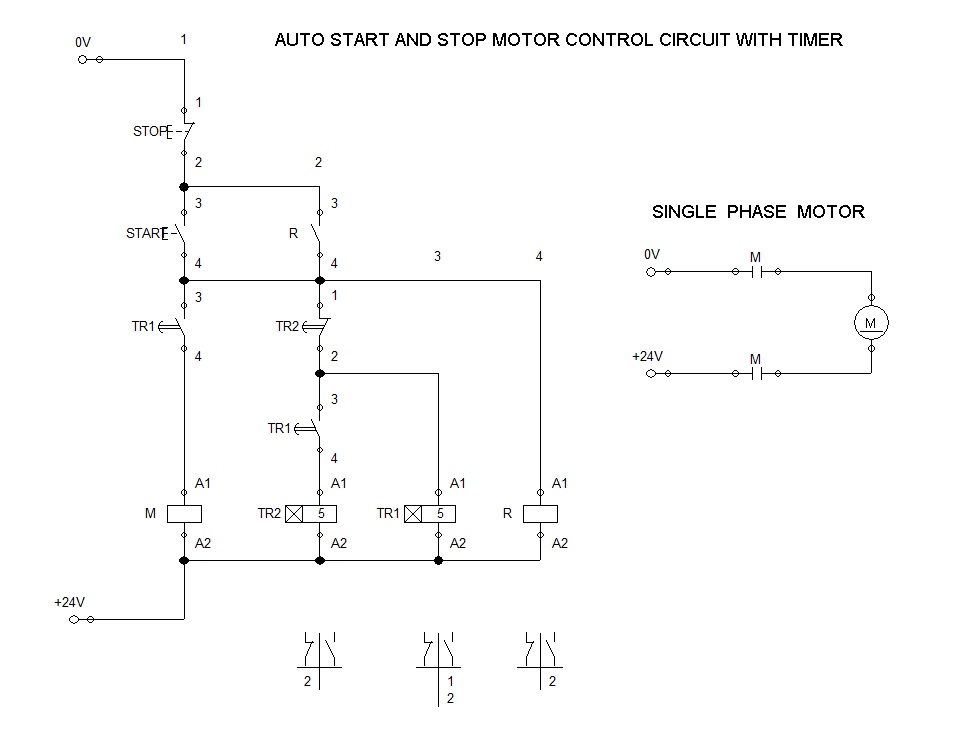
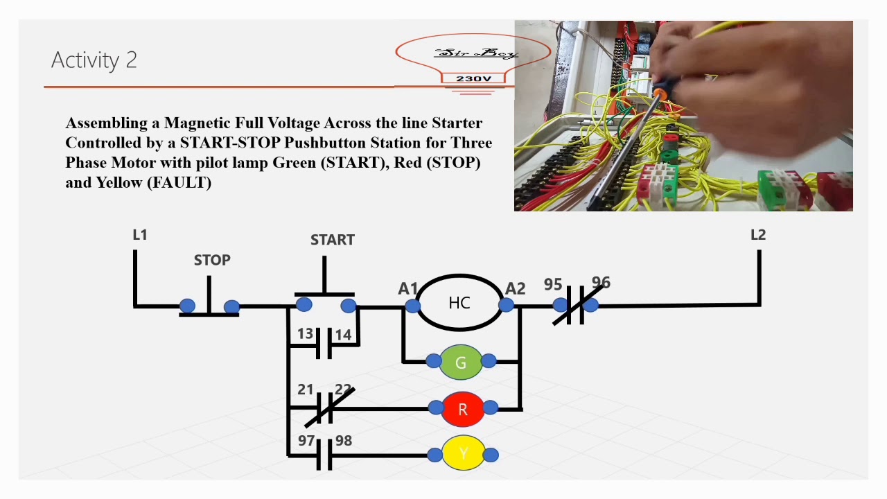
Across The Line Starter Auto Start and Stop Motor Control

2 Wire Start Stop Diagram ios

Simple Start Stop Circuit Diagram
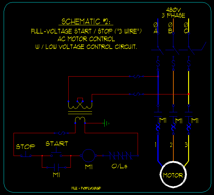
They Could Be Any Of The Preceding Or Following Circuits That Provide Undervoltage Protection.
Specify How Many Buttons Of Each Type Are Required In Your Circuit:
Two Wire Control Or Undervoltage Release Circuits Are Not Applicable Because They Would Be Energized As The Master Stop Button Is Released.
The Complete Diagram Of The One Push Button Start Stop Circuit Includes Several Components That Are Essential For Its Functioning.
Related Post: