Symbols In Mechanical Drawing
Symbols In Mechanical Drawing - The purpose is to convey all the information necessary for manufacturing a product or a part. Web mechanical engineering solution — 8 libraries are available with 602 commonly used mechanical drawing symbols in mechanical engineering solution, including libraries called bearings with 59 elements of roller and ball bearings, shafts, gears, hooks, springs, spindles and keys; For roughness value less than 25μm, the equilateral triangular symbol is used. Symbols used in gd&t callouts. An engineering drawing is a subcategory of technical drawings. Technical standards are the definition and glossary of abbreviations, symbols, and acronyms that may be found on engineering drawings. Engineering drawings use standardised language and symbols. The radius symbol represents half the diameter of a circle or. Web where to find or options to create welding symbols in autocad. Web the drawing abbreviations and symbols of mechanical design and engineering save 0 you may easily identify the abbreviation kg and cm, do you know the meaning of cyl and equi sp on a cnc design? Web the drawing abbreviations and symbols of mechanical design and engineering save 0 you may easily identify the abbreviation kg and cm, do you know the meaning of cyl and equi sp on a cnc design? They are used to help engineers and architects communicate with each other about the design of various objects. On the bottom of the title. Click on the links below to learn more about each gd&t symbol or concept, and be sure to download the free wall chart for a quick reference when at your desk or. Web it is suggested to indicate the surface roughness on drawing by symbols. You can also check out the gd&t symbols and terms on our site. For roughness. There are dozens of different symbols that can be used, but most share a few common elements. Web the drawing abbreviations and symbols of mechanical design and engineering save 0 you may easily identify the abbreviation kg and cm, do you know the meaning of cyl and equi sp on a cnc design? The following is a short list of. Symbols used in gd&t callouts. The following is a short list of symbols that normally appear on a technical drawing and need understanding. The radius symbol represents half the diameter of a circle or. For roughness value less than 25μm, the equilateral triangular symbol is used. You can also check out the gd&t symbols and terms on our site. Web engineering drawing basics explained. You can also check out the gd&t symbols and terms on our site. Often models are used in. Web common blueprint symbols. Web it is suggested to indicate the surface roughness on drawing by symbols. You can even flip between scales on the fly. Use the welding.dwg file in the autocad samples folder: We offer you our tips which we believe are useful for dispelling uncertainty by comparing the symbol with its graphic representation. Web mechanical drawing symbols are used to represent physical objects in a technical drawing. Options for welding symbols are: Web basic and common symbols. Web engineering drawings (aka blueprints, prints, drawings, mechanical drawings) are a rich and specific outline that shows all the information and requirements needed to manufacture an item or product. Web it is suggested to indicate the surface roughness on drawing by symbols. Often models are used in. On the bottom of the title block, the. Often models are used in. Web the drawing abbreviations and symbols of mechanical design and engineering save 0 you may easily identify the abbreviation kg and cm, do you know the meaning of cyl and equi sp on a cnc design? You can even flip between scales on the fly. This makes understanding the drawings simple with little to no. Options for welding symbols are: Web basic types of symbols used in engineering drawings are countersink, counterbore, spotface, depth, radius, and diameter. Often models are used in. Symbols used in gd&t callouts. Web smartdraw provides thousands of mechanical drawing symbols that you can drag and drop, then add lines and text. Web basic types of symbols used in engineering drawings are countersink, counterbore, spotface, depth, radius, and diameter. Web the vector stencils library dimensioning and tolerancing contains 45 symbols of geometric dimensions and mechanical tolerances, geometric symbols, callouts, and text boxes and inserts. Web currently, we have 16 symbols for geometric tolerances, which are categorized according to the tolerance they specify.. Completed symbols are usable in standard. The bis recommended symbols for indicating the surface finish are shown in table a. The symbols and abbreviations covered in this module relate to a few trades and professions. The radius symbol represents half the diameter of a circle or. Technical standards are the definition and glossary of abbreviations, symbols, and acronyms that may be found on engineering drawings. The purpose is to convey all the information necessary for manufacturing a product or a part. You can even flip between scales on the fly. Web how to read symbols in an engineering drawing? We offer you our tips which we believe are useful for dispelling uncertainty by comparing the symbol with its graphic representation. Web where to find or options to create welding symbols in autocad. There are dozens of different symbols that can be used, but most share a few common elements. Use these geometric dimensioning and tolerancing (gd&t) shapes to create annotated mechanical drawings. Gd&t is used to define the nominal (theoretically. This is a technical drawing title block example, and tells you the product designer, which in this case is essentra components. Often models are used in. In the context of cnc (computer numerical control) design, the abbreviations “cyl” and “equi sp” typically refer to specific features or parameters.
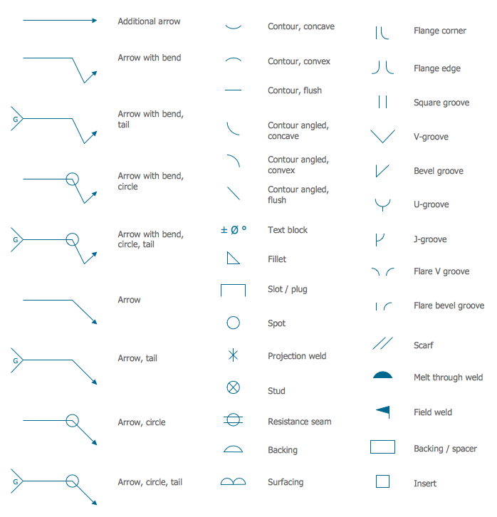
Design Elements Dimensioning and Tolerancing Mechanical design

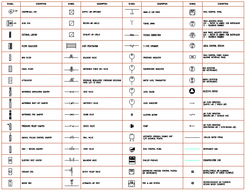
Mechanical Drawing Symbols

Mechanical Engineering Drawing Symbols Pdf Free Download at

Mechanical Engineering Symbols Cadbull

Engineering Drawing Symbols And Their Meanings Pdf at PaintingValley

Mechanical Engineering Solution

Mechanical Engineering Drawing Symbols Pdf Free Download at

Mechanical Engineering Symbols And Their Meanings

Basic Engineering Practice Machine Design & Materials PE Exam Tools

Piping Coordination System Mechanical symbols for Isometric drawings
Symbols Used In Gd&T Callouts.
An Engineering (Or Technical) Drawingis A Graphical Representation Of A Part, Assembly, System, Or Structure And It Can Be Produced Using Freehand, Mechanical Tools, Or Computer Methods.
Web Mechanical Drawing Symbols Are Used To Represent Physical Objects In A Technical Drawing.
Web Some Commonly Used Dimensioning Symbols Include:
Related Post: