Thread Callout On Drawing
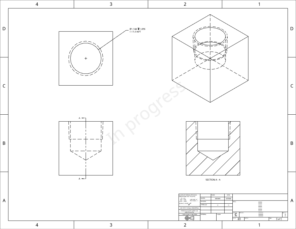
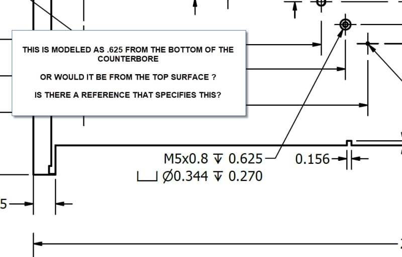
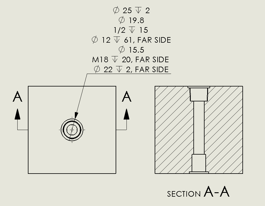
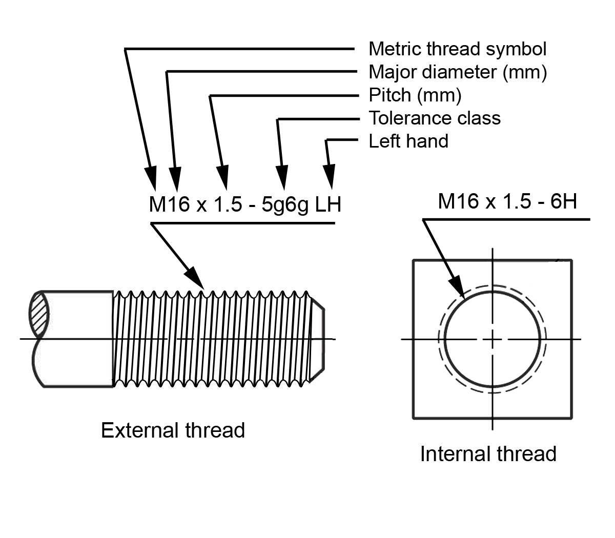
Thread Callout On Drawing - Here are a few important things to remember when specifying threads: When we look at a drill and tap chart, we see that there are two options for this size: Web cosmetic threads in part documents are inserted automatically into drawing views. An ansi drawing is illustrated below: 9 writing notes for threaded holes: Specify threads on a 2d drawing with a thread specification callout (aka thread hole callout) for metric sizes, specify size with the thread pitch (diameter x pitch in mm); A thread callout is also inserted if the drawing document is in ansi standard. Local notes, also referred to as callouts, are included on a drawing to specify information for a specific feature of a component or assembly. The feature being referenced is The difference is one group says also call out diameter of the hole to be drilled to prepare for tapping, second group says don't include diameter of the hole, the thread callout handles it all. Here are a few important things to remember when specifying threads: Web tips for threaded hole callouts. Inch thread and metric thread callout on the engineering drawing. The first time you see a callout can be a little confusing, but it’s pretty straightforward once you know what the numbers are meant to stand for. Which is 3 in the case. Here are a few important things to remember when specifying threads: Web cosmetic threads in part documents are inserted automatically into drawing views. M12 x 1.75 has a 12 mm major diameter and a 1.75. Which is 3 in the case of inch thread and 2 in the case of metric thread from. The difference is one group says also. Threads on tapped and tapered pipe tap holes are indicated by dashed lines for ansi drawings, and the appropriate 3/4 outline for iso drawings. The image below depicts an ansi tapered pipe tap hole drawing: The option with fewer threads per inch is the coarse thread. The first part represents the quantity of the hole. M12 x 1.75 has a. 9 writing notes for threaded holes: Local notes, also referred to as callouts, are included on a drawing to specify information for a specific feature of a component or assembly. A thread note must be included on all threaded parts, with a leader line to the external thread or to an internal thread in the circular view. The callout basically. When we look at a drill and tap chart, we see that there are two options for this size: 6 local notes (callouts) 8 counterbore specification: The difference is one group says also call out diameter of the hole to be drilled to prepare for tapping, second group says don't include diameter of the hole, the thread callout handles it. When we look at a drill and tap chart, we see that there are two options for this size: Web tips for threaded hole callouts. Specify threads on a 2d drawing with a thread specification callout (aka thread hole callout) for metric sizes, specify size with the thread pitch (diameter x pitch in mm); Web cosmetic threads in part documents. (you insert thread callouts in the cosmetic thread propertymanager, but they appear only in drawing documents.) thread callouts are not used in iso, jis, or other standards, but you can. Web screws come in a wide variety of shapes and sizes, so thread callouts are used to help identify them. Local notes, also referred to as callouts, are included on. Web screws come in a wide variety of shapes and sizes, so thread callouts are used to help identify them. 9 writing notes for threaded holes: Web for example, a drawing has a thread callout of ¼”. A thread callout is also inserted if the drawing document is in ansi standard. Therefore, thread notes are needed to provide the required. In the above tap hole callout, we have given two callouts to understand it in both metric and inch systems. A thread note must be included on all threaded parts, with a leader line to the external thread or to an internal thread in the circular view. External thread notes are given in the longtitudinal view. 9 writing notes for. This corresponds to a ¼” nominal diameter thread with either 20 threads per inch or 28 threads per inch. Web threads are only symbolically represented on drawings; Inch thread and metric thread callout on the engineering drawing. There are 3 parts for each callout. The image below depicts an ansi tapered pipe tap hole drawing: The image below depicts an ansi tapered pipe tap hole drawing: Local notes, also referred to as callouts, are included on a drawing to specify information for a specific feature of a component or assembly. In the above tap hole callout, we have given two callouts to understand it in both metric and inch systems. Web screws come in a wide variety of shapes and sizes, so thread callouts are used to help identify them. 6 local notes (callouts) 8 counterbore specification: M12 x 1.75 has a 12 mm major diameter and a 1.75. Web here is my specific question about the two schools of thought, using a typical thread callout. The option with fewer threads per inch is the coarse thread. This corresponds to a ¼” nominal diameter thread with either 20 threads per inch or 28 threads per inch. An ansi drawing is illustrated below: We can visualize each hole’s tolerance zone as a cylinder with a diameter of ø.016 inches, having an axis perfectly perpendicular to datum plane a. Web specification of metric threads: Inch thread and metric thread callout on the engineering drawing. The first time you see a callout can be a little confusing, but it’s pretty straightforward once you know what the numbers are meant to stand for. Web for example, a drawing has a thread callout of ¼”. There are 3 parts for each callout.
Dimensioning threaded fasteners Engineering Design McGill University

How to Draw Threaded Hole in Autocad 2d Adkins Fricaunt
Hole/Thread Callout
Threaded Hole Callout Standard Home Interior Design
SOLIDWORKS 2018 Advanced Hole & Callout Tutorial Innova Systems

Using Cosmetic Threads in SOLIDWORKS Parts and Drawings

3D Printing Threads (Cosmetic/Virtual Threads vs Real 3D Threads)

Using Cosmetic Threads in SOLIDWORKS Parts and Drawings

Thread callout in drawing Siemens UG/NX EngTips
Dimensioning threaded fasteners Engineering Design McGill University
External Thread Notes Are Given In The Longtitudinal View.
Web Cosmetic Threads In Part Documents Are Inserted Automatically Into Drawing Views.
The Callout Basically Corresponds To The Length And Diameter Of The Screw’s Shaft.
Here Are A Few Important Things To Remember When Specifying Threads:
Related Post: