Typ In Engineering Drawing
Typ In Engineering Drawing - Web “typ” is one of the most common abbreviations you’ll see in a set of construction documents. Web the technical engineering drawing abbreviations we outline here are the terms used in the manufacturing and inspection of parts and assemblies. You’ll find it not only in architectural drawings but in all of the other trades’ drawings as well. Ref on drawings is generally defined as reference. One can pack a great deal of information into an isometric drawing. Web the typ statement was and perhaps still is an architecture standard and not a mechanical standard. Web asme y14.24, “drawings types and applications of engineering drawings”, was adopted on. The typ callout was often used in wall sections to reference typical or common elements of a section. This makes understanding the drawings simple with little to no personal interpretation possibilities. You can find the list of common engineering drawing abbreviations. This makes understanding the drawings simple with little to no personal interpretation possibilities. Ref on drawings is generally defined as reference. This is identical to a feature which is identified as 2x or 5x. Basically, this type of drawing aims at clearly capturing all the geometric features of products and. Web what is 'typ' in engineering? However, if the object in figure 2 had a hole on the back. Engineers use 'typ' to denote the commonly accepted dimensional values of various components in their designs. Often models are used in conjunction with engineering drawings. If you have a part with 500.250 holes and a single.260 hole, you might dimension the.260 hole and label the other 500. You can find the list of common engineering drawing abbreviations. Web typ on drawings is generally defined as typical. In other words, it means that the other 7 holes are that size also.' Engineers use 'typ' to denote the commonly accepted dimensional values of various components in their designs. Web typ means it's typical to all identical features. There are other information blocks like it, but the title block serves as the context in which the drawing should be perceived. If you have a part with 500.250 holes and a single.260 hole, you might dimension the.260 hole and label the other 500 as a group as.250 typ (x500). Web engineering drawing abbreviations and symbols are used to communicate. Ref on drawings is generally defined as reference. Web “typ” is one of the most common abbreviations you’ll see in a set of construction documents. Web engineering drawing abbreviations and symbols are used to communicate and detail the characteristics of an engineering drawing. These dimensions are to be used as reference only. There are other information blocks like it, but. 14 february 2000 for use by the department of defense (dod). Web an engineering drawing (also named as mechanical drawing, manufacturing blueprints, drawings, dimensional prints, and more) refers to one of the technical drawings, which helps to define engineering products’ requirements. Web typ means 'other features share the same characteristic. A typical dimension callout will occasionally be followed by a. This is often used when there are similar features, and to avoid unnecessary dimensioning by the draftsperson. Name and address of the company or agency who prepared or owns the drawing. Typ is simply an abbreviation for “typical.” A typical dimension callout will occasionally be followed by a 2x, 5x or similar, to specify the quantity of features which are. Web an engineering (or technical) drawing is a graphical representation of a part, assembly, system, or structure and it can be produced using freehand, mechanical tools, or computer methods. However, if the object in figure 2 had a hole on the back. The typ callout was often used in wall sections to reference typical or common elements of a section.. You’ll find it not only in architectural drawings but in all of the other trades’ drawings as well. These dimensions are to be used as reference only. Web typical on an engineering drawing identifies a repeated feature. Could also be written as 14x 0.25 if you had 14 holes each 0.25 in dia. Name and address of the company or. Web typ means 'other features share the same characteristic. Ref on drawings is generally defined as reference. The purpose is to convey all the information necessary for manufacturing a product or a part. In large or complicated technical drawings, coordinates are commonly employed and positioned along the. Usually, a number of drawings are necessary to completely specify even a simple. Web an engineering drawing (also named as mechanical drawing, manufacturing blueprints, drawings, dimensional prints, and more) refers to one of the technical drawings, which helps to define engineering products’ requirements. Unlike a model, engineering drawings offer more specific detail and requirements, such as: Could also be written as 14x 0.25 if you had 14 holes each 0.25 in dia. However, if the object in figure 2 had a hole on the back. You can find the list of common engineering drawing abbreviations. This is often used when there are similar features, and to avoid unnecessary dimensioning by the draftsperson. For example, if the drawing shows 8 holes on a bolt circle, and just one is dimensioned, with typ or (typ) following the dimension label, it means that that hole is typical of all 8 holes; If you have a part with 500.250 holes and a single.260 hole, you might dimension the.260 hole and label the other 500 as a group as.250 typ (x500). Engineering drawings use standardised language and symbols. Proposed changes by dod activities must be submitted to the dod adopting activity: In other words, it means that the other 7 holes are that size also.' One can pack a great deal of information into an isometric drawing. So if there's a few bolt patterns and only one is dimensioned with typ on all dims, then all the bolt patterns are exactly the same. Typ is the short form of typical in engineering drawings. What does typ (typical) mean on a drawing? It's a technical abbreviation used to indicate the standard dimensions, tolerances, and specifications of specific components or devices.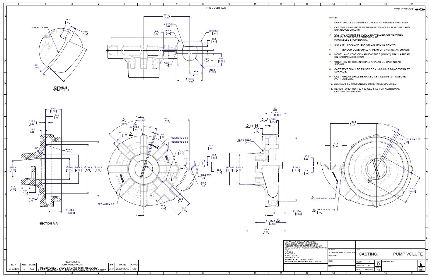
Engineering Drawings Justin R. Palmer

a. Typical engineering drawing with dimensioning lines and text, and b
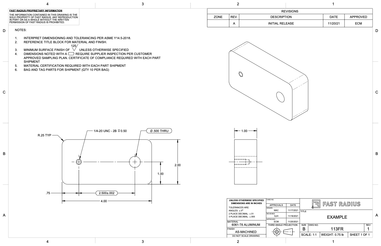
What to Include in Your Engineering Drawing Fast Radius
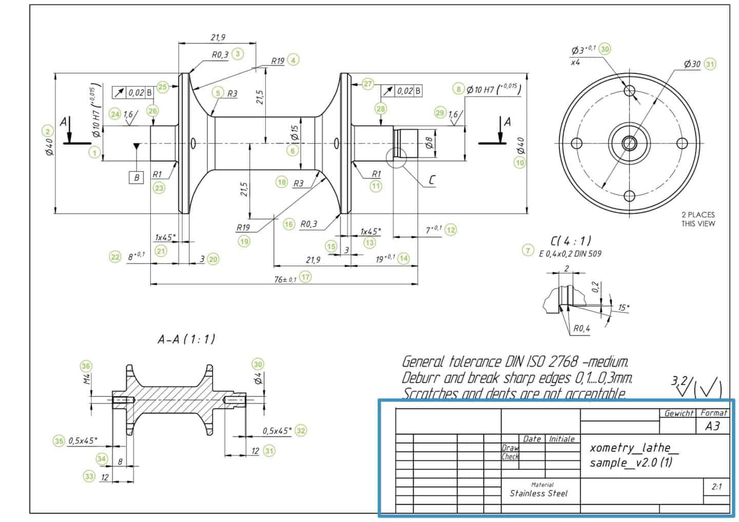
How To Prepare A Perfect Technical Drawing Xometry Europe

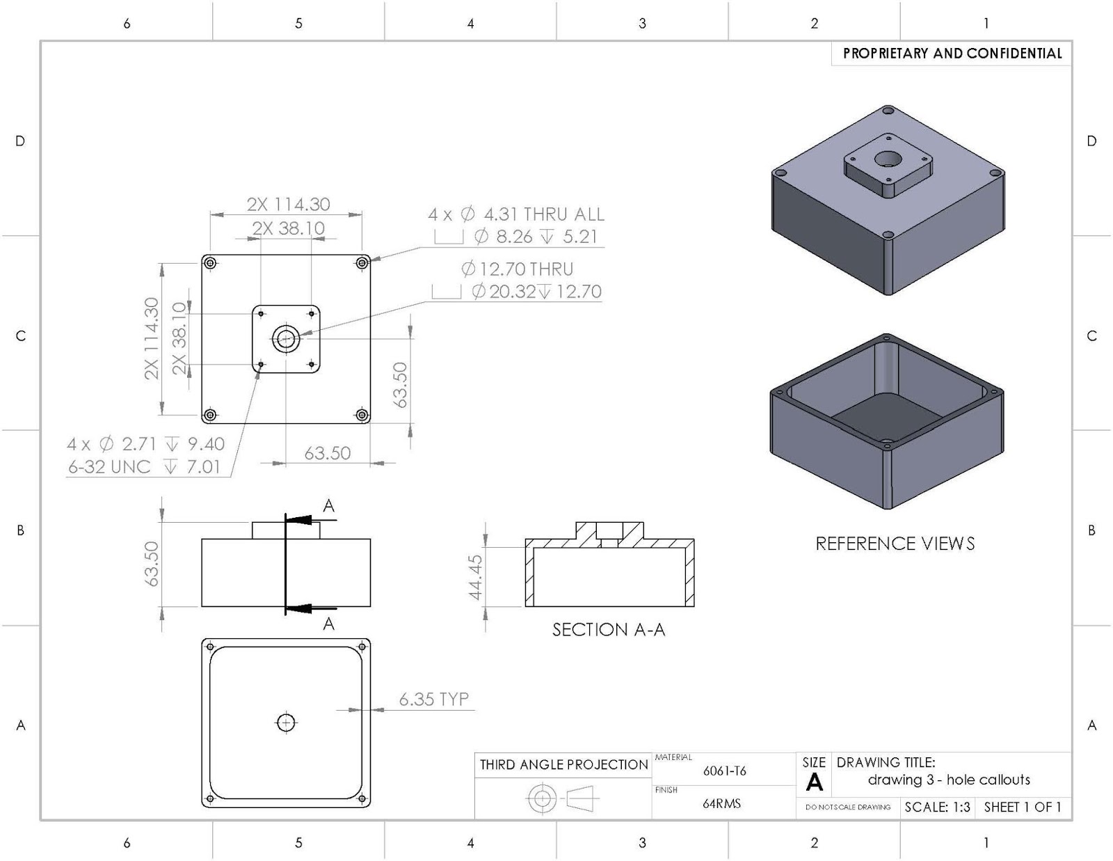
Types Of Dimensions In Engineering Drawing at GetDrawings Free download

Engineering drawing symbols TYP שרטוט סימון אוביקט טיפוסי YouTube

Types Of Dimensions In Engineering Drawing at GetDrawings Free download

Types Of Dimensions In Engineering Drawing at GetDrawings Free download

6 types of engineering drawings
How To Make a Great Engineering Drawing Manufacturers Will Understand
Web Any Engineering Drawing Should Show Everything:
A Common Use Is To Specify The Geometry Necessary For The Construction Of A Component And Is Called A Detail Drawing.
Web The Technical Engineering Drawing Abbreviations We Outline Here Are The Terms Used In The Manufacturing And Inspection Of Parts And Assemblies.
Web Typ On Drawings Is Generally Defined As Typical.
Related Post: