Types Of Lines In Engineering Drawing
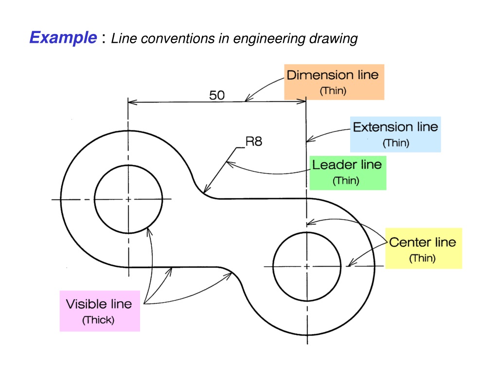
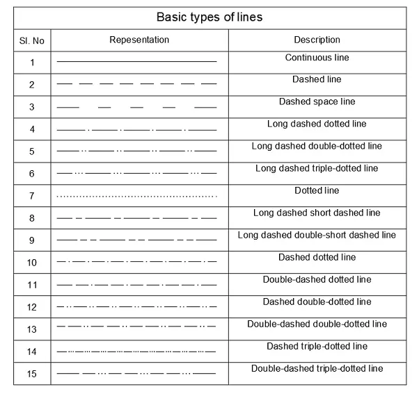
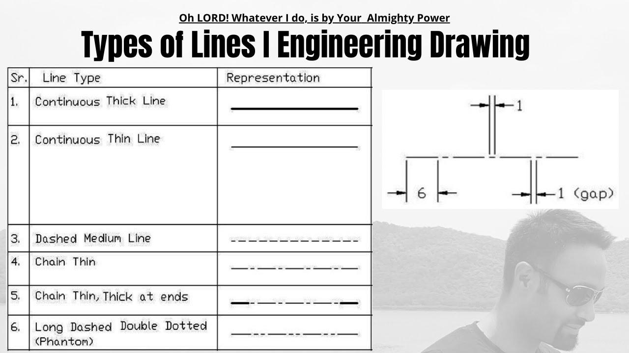
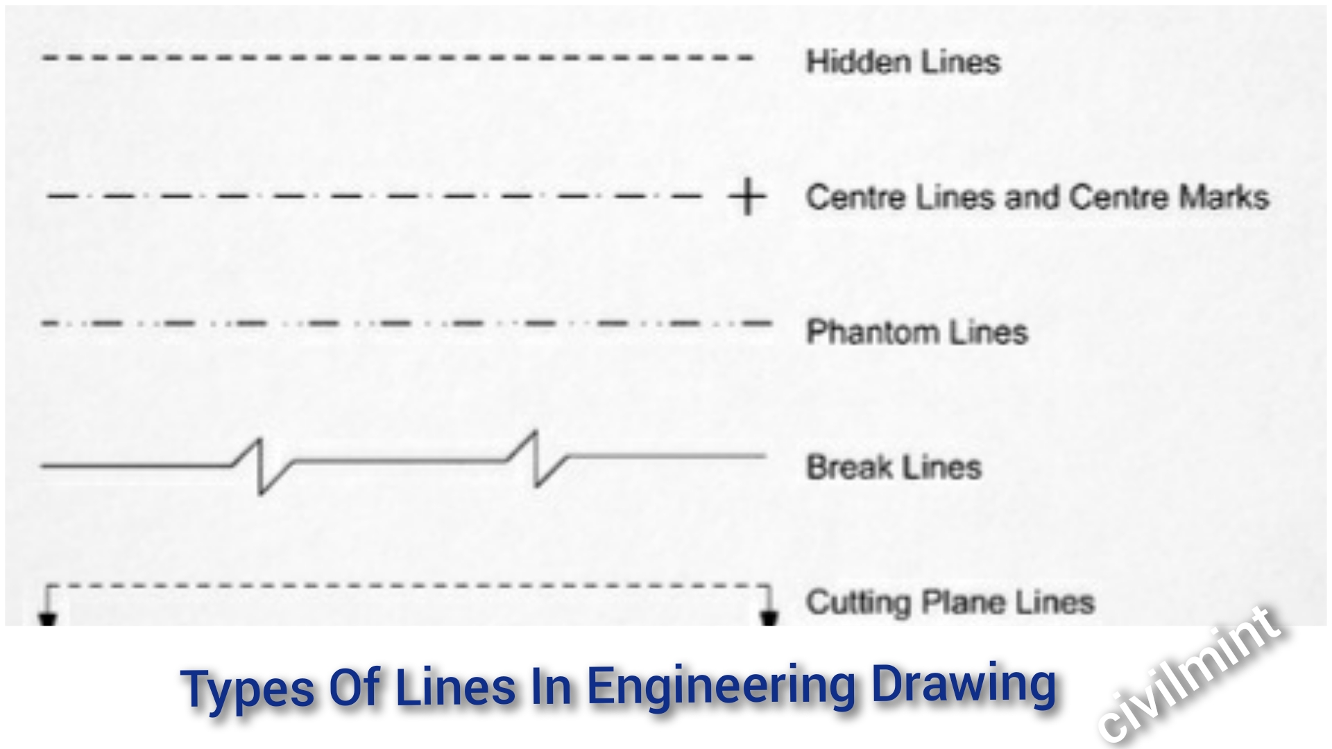
Types Of Lines In Engineering Drawing - Web the dashed line may be either thick or thin, but only one type (thick or thin) should be used on a single drawing or set of drawings. Web object lines (figure 3) are the most common lines used in drawings. Web the standard line types used in technical drawings are center lines are used: Web there are 12 types of lines usually used in engineering drawing. The purpose is to convey all the information necessary for manufacturing a product or a part. Generally, there are 11 basic types of lines. These thick, solid lines show the visible edges, corners, and surfaces of a part. Thin chain line the thin chain line is used to indicate center lines, the lines of symmetry and also trajectories. Engineering drawings use standardised language and symbols. Solid line to show visible shapes, edges, and outlines. Web 18.06.2020 by andreas velling engineering drawing basics explained an engineering drawing is a subcategory of technical drawings. Visible lines hidden lines section lines center lines dimension lines extension lines leader lines cutting plane lines break lines phantom lines borderlines arrowheads visible lines they are dark and thick lines of any engineering design drawing. Web line styles and types standard. Each kind of line has a definite form and “weight”. To represent symmetry, to represent paths of motion, to mark the centers of circles and the axes of symmetrical parts, such as cylinders and bolts. A variety of line styles graphically represent physical objects. Weight refers to line thickness or width. Generally, there are 11 basic types of lines. Object lines stand out on the drawing and clearly define the outline and features of the object. To represent symmetry, to represent paths of motion, to mark the centers of circles and the axes of symmetrical parts, such as cylinders and bolts. Web the dashed line may be either thick or thin, but only one type (thick or thin) should. Solid line to show visible shapes, edges, and outlines. These thick, solid lines show the visible edges, corners, and surfaces of a part. Thin chain line the thin chain line is used to indicate center lines, the lines of symmetry and also trajectories. Web 18.06.2020 by andreas velling engineering drawing basics explained an engineering drawing is a subcategory of technical. A variety of line styles graphically represent physical objects. Solid line to show visible shapes, edges, and outlines. Visible lines hidden lines section lines center lines dimension lines extension lines leader lines cutting plane lines break lines phantom lines borderlines arrowheads visible lines they are dark and thick lines of any engineering design drawing. Each kind of line has a. Visible lines are the most fundamental type of lines used in engineering drawings. Object lines stand out on the drawing and clearly define the outline and features of the object. Broken line of short dashes to show alternate positions or movement of a part. Web line styles and types standard engineering drawing line types. Engineering drawings use standardised language and. These thick, solid lines show the visible edges, corners, and surfaces of a part. Broken line of short dashes to show alternate positions or movement of a part. Thin chain line the thin chain line is used to indicate center lines, the lines of symmetry and also trajectories. Visible lines are the most fundamental type of lines used in engineering. Web the dashed line may be either thick or thin, but only one type (thick or thin) should be used on a single drawing or set of drawings. Web following are the different types of lines used in engineering drawing: Thin chain line the thin chain line is used to indicate center lines, the lines of symmetry and also trajectories.. Web the standard line types used in technical drawings are center lines are used: Thin chain line the thin chain line is used to indicate center lines, the lines of symmetry and also trajectories. Web following are the different types of lines used in engineering drawing: Broken lines of long and short dashes to show hidden object lines not visible. Web the dashed line may be either thick or thin, but only one type (thick or thin) should be used on a single drawing or set of drawings. Web object lines (figure 3) are the most common lines used in drawings. Broken lines of long and short dashes to show hidden object lines not visible to the eye. Visible lines. A variety of line styles graphically represent physical objects. Visible lines hidden lines section lines center lines dimension lines extension lines leader lines cutting plane lines break lines phantom lines borderlines arrowheads visible lines they are dark and thick lines of any engineering design drawing. Object lines stand out on the drawing and clearly define the outline and features of the object. Web object lines (figure 3) are the most common lines used in drawings. Thin chain line the thin chain line is used to indicate center lines, the lines of symmetry and also trajectories. The purpose is to convey all the information necessary for manufacturing a product or a part. Web 18.06.2020 by andreas velling engineering drawing basics explained an engineering drawing is a subcategory of technical drawings. Web since technical drawings are made of lines, it is logical that the first step in learning to “read” a drawing is to learn the meaning of each kind of line. Broken line of short dashes to show alternate positions or movement of a part. To represent symmetry, to represent paths of motion, to mark the centers of circles and the axes of symmetrical parts, such as cylinders and bolts. Engineering drawings use standardised language and symbols. Visible lines are the most fundamental type of lines used in engineering drawings. Web line styles and types standard engineering drawing line types. Web there are 12 types of lines usually used in engineering drawing. Weight refers to line thickness or width. Broken lines of long and short dashes to show hidden object lines not visible to the eye.
What are Lines & Types Of Lines in Engineering Drawing ? YouTube
PPT Chapter 1 Overview of an Engineering Drawing PowerPoint

leader line in engineering drawing howtobetteryourselfeveryday
Types Of Line In Engineering No.1 Detailed Guide To Line Types

10 Different Types of Lines Used In Engineering Drawing
Theory of Line Types Types of Lines in Engineering Drawing 3.0

Andromeda CAD Basics of Engineering Drawing

INCH Technical English pictorial engineering drawing line types

Types of lines use in engineering graphics Various types of lines
Types Of Lines In Engineering Drawing
Each Kind Of Line Has A Definite Form And “Weight”.
Let’s Explore Some Of The Most Common Types Of Lines Used In Engineering Drawings:
Web The Standard Line Types Used In Technical Drawings Are Center Lines Are Used:
Web Following Are The Different Types Of Lines Used In Engineering Drawing:
Related Post: