Ultrasound Transducer Drawing
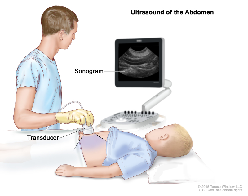
Ultrasound Transducer Drawing - This part will learn about image orientation while. Web 4 100 mhz array on zinc oxide. Web typical transducers used in clinical ultrasound include linear array, phased array, and curvilinear array, which has multiple configurations and frequencies depending on the application needed. 6 schematic drawing of a sapphire lens with a piezoelectric layer and the distribution of the sound field. The device then receives the echoes and transmits them to a computer that converts them into an image called a sonogram. Web the illustration shows a schematic drawing of wave length, pressure and amplitude. The ultrasonographer coordinates the interaction of all four elements during an examination. Web the ultrasonic imaging system consists of ultrasonic transducers and an imaging system. 17 april 2022 41, article number: The imaging system controls the ultrasonic transducer in order to transmit and receive the ultrasound, and creates an ultrasound image with a set of data from the transducer. Web 4 100 mhz array on zinc oxide. In this process, this transducer measures the distance of the object not by the intensity of the sound. The transducer face’s crystals and structure's arrangement determine the area and shape of the image produced. Location and orientation of the ultrasound transducer for echocardiography, over the anterior intercostal spaces. Please contact us for. Web basic transducer formats are sector, linear array, and curved array ( fig. G., a wall or prey) to the sender (bat) can be computed accurately, assuming that the sound velocity is known. Web the goal is to obtain optimal ultrasound images through an understanding of the equipment setup, transducer (probe) selection, terminology, and general scanning principles. In this process,. These transducers send the electrical signals to the object and once the signal strikes the object then it reverts to the transducer. The ultrasonographer coordinates the interaction of all four elements during an examination. The operator must therefore keep in mind the orientation of the ribs wherever the transducer is being used. The first step in designing a transducer is. 1.1 a, this figure describes ultrasound imaging using the four key elements involved: The operator must therefore keep in mind the orientation of the ribs wherever the transducer is being used. This part will learn about image orientation while. Web • lead zirconate titanate, or pzt, is the piezoelectric material used in nearly all medical ultrasound transducers • it is. 5 40 mhz array on pzt with bonded contacts. Web • lead zirconate titanate, or pzt, is the piezoelectric material used in nearly all medical ultrasound transducers • it is a ceramic ferroelectric crystal exhibiting a strong piezoelectric effect and can be manufactured in nearly any shape • the most common transducer shapes are the circle, for single crystal transducer. Web an ultrasound transducer converts electrical energy into mechanical (sound) energy and back again, based on the piezoelectric effect. Web the goal is to obtain optimal ultrasound images through an understanding of the equipment setup, transducer (probe) selection, terminology, and general scanning principles. Understand the operation of these devices. List the basic components that are used in the construction of. Web an ultrasound transducer converts electrical energy into mechanical (sound) energy and back again, based on the piezoelectric effect. These transducers are optimal for examining larger organs from between the ribs. Web overcome this effect is to rotate the transducer so that it lies entirely within the space between the ribs. The first step in designing a transducer is to. The transducer works by producing sound waves that bounce off body tissues and create echoes. Web the ultrasonic imaging system consists of ultrasonic transducers and an imaging system. 6 mhz to 1 ghz. The device then receives the echoes and transmits them to a computer that converts them into an image called a sonogram. The operator must therefore keep in. It consists of five main components: Web some animal species such as bats can perceive ultrasound and use it for echolocation: Web these ultrasonic transducer technical notes provide an overview of the ultrasonic principles that impact the design and functioning of ultrasonic transducers. G., a wall or prey) to the sender (bat) can be computed accurately, assuming that the sound. It consists of five main components: Web the illustration shows a schematic drawing of wave length, pressure and amplitude. Web 4 100 mhz array on zinc oxide. The imaging system controls the ultrasonic transducer in order to transmit and receive the ultrasound, and creates an ultrasound image with a set of data from the transducer. Web typical transducers used in. The transducer works by producing sound waves that bounce off body tissues and create echoes. Best solution, in the absence of information, is to measure its impedance while powered from any suitable generator, at low voltage. It consists of five main components: 38 ( 2022 ) download pdf journal of nondestructive evaluation aims and scope submit manuscript mohammad javad ranjbar naserabadi & sina sodagar 491. Location and orientation of the ultrasound transducer for echocardiography, over the anterior intercostal spaces. Web ultrasonic transducers work at resonant frequency (40 khz for this one), at which, due to mechanical resonance, their impedance changes greatly. Understand the operation of these devices. Web designing an ultrasonic transducer. Web an ultrasound transducer converts electrical energy into mechanical (sound) energy and back again, based on the piezoelectric effect. Outlined is a structured, standardized approach necessary to obtain complete information when doing intraoperative ultrasound. Web 4 100 mhz array on zinc oxide. This part will learn about image orientation while. Understand how ultrasound images are formed. The device then receives the echoes and transmits them to a computer that converts them into an image called a sonogram. The transducer face’s crystals and structure's arrangement determine the area and shape of the image produced. These transducers send the electrical signals to the object and once the signal strikes the object then it reverts to the transducer.
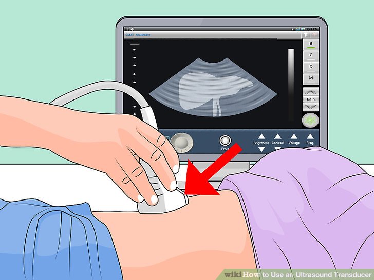
How to Use an Ultrasound Transducer

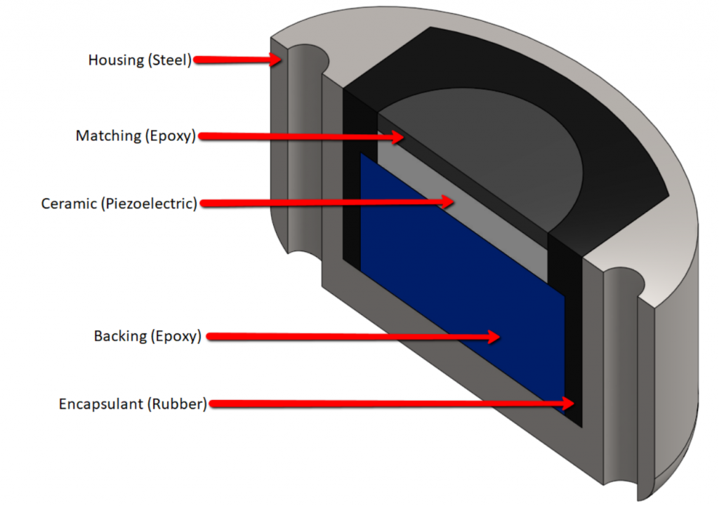
Ultrasonics Transducers Piezoelectric Hardware CTG Technical Blog

An illustration of ultrasound transducers in an ultrasound system

The ultrasound transducer ECG & ECHO

Positioning of the ultrasound transducer for the three views

Ultrasound Drawing at GetDrawings Free download
![]()
Iconos De Los Transductores Del Ultrasonido Ilustración del Vector

Piezoelectric Transducer Simulation with OnScale Ultrasonic Sensor
![]()
Ultrasound Pictogram. Line Art Icon of Display with Transducer. Black

Schematic drawing of the ultrasound probe positions during the FASH
Web The Goal Is To Obtain Optimal Ultrasound Images Through An Understanding Of The Equipment Setup, Transducer (Probe) Selection, Terminology, And General Scanning Principles.
17 April 2022 41, Article Number:
G., A Wall Or Prey) To The Sender (Bat) Can Be Computed Accurately, Assuming That The Sound Velocity Is Known.
By Measuring The Time Between Sending And Receiving (After Partial Reflection On A Surface) Ultrasonic Waves, The Distance Of An Object (E.
Related Post: